


36 18-CD19D6-32
Installer’s Guide
furnace reaches the maximum outlet temperature as
shown on the rating plate, the burners must shut off. If
they do not shut off after a reasonable time and over-
heating is evident, a faulty limit switch is probable and
the limit switch must be replaced. After checking the
operation of the limit control, be sure to remove the pa-
per or cardboard from the return air inlet. Refer to Ser-
vice Facts for additional instructions.
NOTE TO INSTALLER
Review the following warnings with the owner. Review
contents of USER’S INFORMATION MANUAL with the
owner.
AIRFLOW ADJUSTMENT
Check inlet and outlet air temperatures to make sure
they are within the ranges specified on the furnace rat-
ing nameplate. If the airflow needs to be increased or
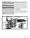
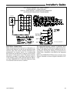
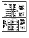
decreased, see the wiring diagram for information on
changing the speed of the blower motor.
▲
WARNING
!
Disconnect power to the unit before removing the
blower door.
Failure to follow this warning could result in property
damage, personal injury or death.
This unit is equipped with a blower door switch which
cuts power to the blower and gas valve causing shut-
down when the door is removed. Operation with the
door removed or ajar can permit the escape of danger-
ous fumes. All panels must be securely closed at all
times for safe operation of the furnace.
INDOOR BLOWER TIMING
Heating: The integrated furnace control module con-
trols the indoor blower. The blower start is fixed at 45
seconds after ignition. The FAN-OFF period is field se-
lectable by dip switches at 60, 100, 140, or 180 seconds.
The factory setting is 100 seconds (See wiring diagram).
Cooling: The fan delay off period is factory set at 0 sec-
onds. The option for 80 second delay off is field select-
able (See wiring diagram).
ROOM AIR THERMOSTAT
HEAT ANTICIPATOR ADJUSTMENT
Set the thermostat heat anticipator according to the
current flow measured, or the settings found in the
notes on the furnace wiring diagram (found in the SER-
VICE FACTS or inside the furnace casing).
INSTRUCTIONS TO THE OWNERS
In the event that electrical, fuel, or mechanical
failures occur, the owner should immediately
turn the gas supply off at the manual gas valve,
located in the burner compartment. Also turn off
electrical power to the furnace and contact the
service agency designated by your dealer.
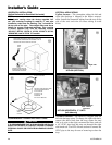
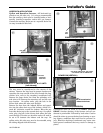
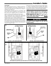
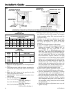
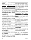
To shut off.
For complete shut-down: Flip the switch on the main
gas valve to the “OFF” position, (See Figure 58 & 59).
Disconnect the electrical supply to the unit.
▲
CAUTION
!
If this is done during the cold weather months, provi-
sions must be taken to prevent freeze-up of all water
pipes and water receptacles.
Failure to follow this warning could result in property
damage.
Whenever your house is to be vacant, arrange to
have someone inspect your house for proper tem-
perature. This is very important during freezing
weather. If for any reason your furnace should
fail to operate damage could result, such as fro-
zen water pipes.
SEQUENCE OF OPERATION
Thermostat call for heat
R and W thermostat contacts close signaling the control
module to run its self-check routine. After the control
module has verified that the pressure switch contacts
are open and the limit switch(es) contacts are closed,
the draft blower will be energized.
As the induced draft blower comes up to speed, the
pressure switch contacts will close and the ignitor warm
up period will begin. The ignitor will heat for approxi-
mately 20 seconds, then the gas valve is energized to
permit gas flow to the burners. The flame sensor con-
firms that ignition has been achieved.
After the flame sensor confirms within a 4 second trial
period that ignition has been achieved, the delay to fan
ON period begins timing. After approximately 45 sec-
onds the indoor blower motor will be energized and con-
tinue to run during the heating cycle.
When the thermostat is satisfied, R and W thermostat
contacts open, the gas valve will close, the flames will
extinguish, and the induced draft blower will be de-en-
ergized. The indoor blower motor will continue to run
for the fan off period (Field selectable at 60, 100, 140 or
180 seconds), then be de-energized by the control mod-
ule.
CONTROL AND SAFETY SWITCH ADJUSTMENTS
LIMIT SWITCH CHECK OUT
The limit switch is a safety device designed to close the
gas valve should the furnace become overheated. Since
proper operation of this switch is important to the
safety of the unit, it must be checked out on initial
start up by the installer.
To check for proper operation of the limit switches, set
the thermostat to a temperature higher than the indi-
cated temperature to bring on the gas valve. Restrict
the airflow by blocking the return air (disconnecting the
indoor blower may trip the inducer limit). When the