


34 18-CD19D6-32
Installer’s Guide
HIGH ALTITUDE DERATE
Input ratings (BTUH) of these furnaces are based on
sea level operation and should not be changed at eleva-
tions up to 2,000 ft.
If the installation is 2,000 ft. or above, the furnace input
rate (BTUH) shall be reduced 4% for each 1,000 ft.
above sea level. The furnace input rate shall be checked
by clocking the gas flow rate (CFH) and multiplying by
the heating value obtained from the local utility sup-
plier for the gas being delivered at the installed altitude.
Input rate changes can be made by adjusting the mani-
fold pressure (min 3.0 - max 3.7 in. W.C. - Natural Gas)
or changing orifices (orifice change may not always be
required). If the desired input rate can not be achieved
with a change in manifold pressure, then the orifices
must be changed. LP installations will require an orifice
change.
Installation of this furnace at altitudes above 2,000 ft.
(610m) shall be in accordance with the local codes, or in
the absence of local codes, the National Fuel Gas Code,
ANSI Z223.1/ NFPA 54 or National Standard of
Canada, Natural Gas and Propane Installation Code,
CSA 149.1. Installation of this furnace at altitudes
above 2,000 ft. (610m) shall be made in accordance with
the listed high Altitude Conversion Kit available with
this furnace.
IMPORTANT:
Re-install the propane orifices to the same depth as the
orifices supplied with the equipment.
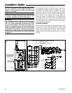
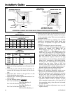
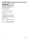
GAS FLOW IN CUBIC FEET PER HOUR
2 CUBIC FOOT DIAL
SEC. FLOW SEC. FLOW SEC. FLOW SEC. FLOW
8 900 29 248 50 144 82 88
9 800 30 240 51 141 84 86
10 720 31 232 52 138 86 84
11 655 32 225 53 136 88 82
12 600 33 218 54 133 90 80
13 555 34 212 55 131 92 78
14 514 35 206 56 129 94 76
15 480 36 200 57 126 96 75
16 450 37 195 58 124 98 73
17 424 38 189 59 122 100 72
18 400 39 185 60 120 104 69
19 379 40 180 62 116 108 67
20 360 41 176 64 112 112 64
21 343 42 172 66 109 116 62
22 327 43 167 68 106 120 60
23 313 44 164 70 103 124 58
24 300 45 160 72 100 128 56
25 288 46 157 74 97 132 54
26 277 47 153 76 95 136 53
27 267 48 150 78 92 140 51
28 257 49 147 80 90 144 50
TABLE 16
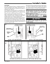
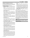
U
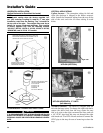
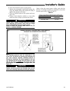
ROTATE THE FRONT
COVER INWARD
MAKING SURE THAT
ALL SIDE FLANGES
ARE OUTSIDE OF THE
BOX.
INSERT THE TOP
FLANGE OF THE FRONT
COVER UNDER THE LIP
INSIDE THE BOX
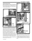
ALL SIDE FLANGES
MUST BE OUTSIDE OF
THE BOX
ROTATE THE FRONT
COVER AS SHOWN