


20 18-CD19D6-32
Installer’s Guide
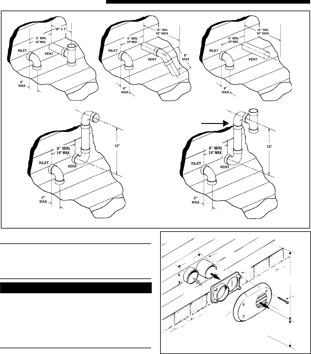
HORIZONTAL VENTING
NOTE:
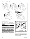
Vent termination kit BAYAIR30AVENTA or
BAYVENT200B may be used instead of the horizontal
and vertical termination options shown in the follow-
ing figures.
▲
CAUTION
!
When the vent pipe is exposed to temperatures below
freezing, i.e., when it passes through unheated spaces,
etc., the pipe must be insulated with 1/2 inch (22.7 mm)
thick Armaflex-type insulation or equal. If the space is
heated sufficiently to prevent freezing, then the insula-
tion would not be required. If domestic water pipes are
not protected from freezing then it is assumed the
space meets the condition of a heated space.
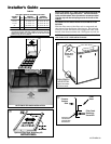
HORIZONTAL VENTING THROUGH WALL
These furnaces may be installed as direct vent (as
shipped) or as nondirect vent. Installation must
conform to national, state, and local codes.
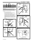
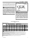
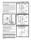
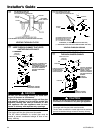
POSSIBLE CONFIGURATIONS FOR TWO PIPE VENTING SYSTEMS
ELBOW AND TEE MUST
BE AS CLOSE TO-
GETHER
AS POSSIBLE
k
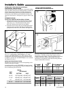
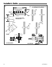
The vent & inlet terminals must be located at least 12"
minimum above normally expected snow accumulation
level.
Avoid areas where staining or condensate drippage may
be a problem.
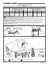
Location of the vent/ wind terminal should be chosen to
meet the requirements of Figure 27 for either direct or
non-direct vent applications.
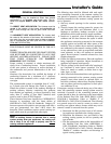
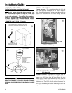
VENT
COMBUSTION
AIR
VENT
VENT
PLATE
VENT
CAP
12" MINIMUM
TO OVERHANG
MAINTAIN 12" (18" FOR CANADA) MINIMUM
CLEARANCE ABOVE HIGHEST ANTICIPATED
SNOW LEVEL OR GRADE WHICHEVER IS GREATER
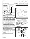
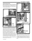
SCREWS
(4 req.)
ANCHORS
(4 req.)
7.2"
3.2"
BAYVENT200B
l