18-CD19D6-32 11
Installer’s Guide
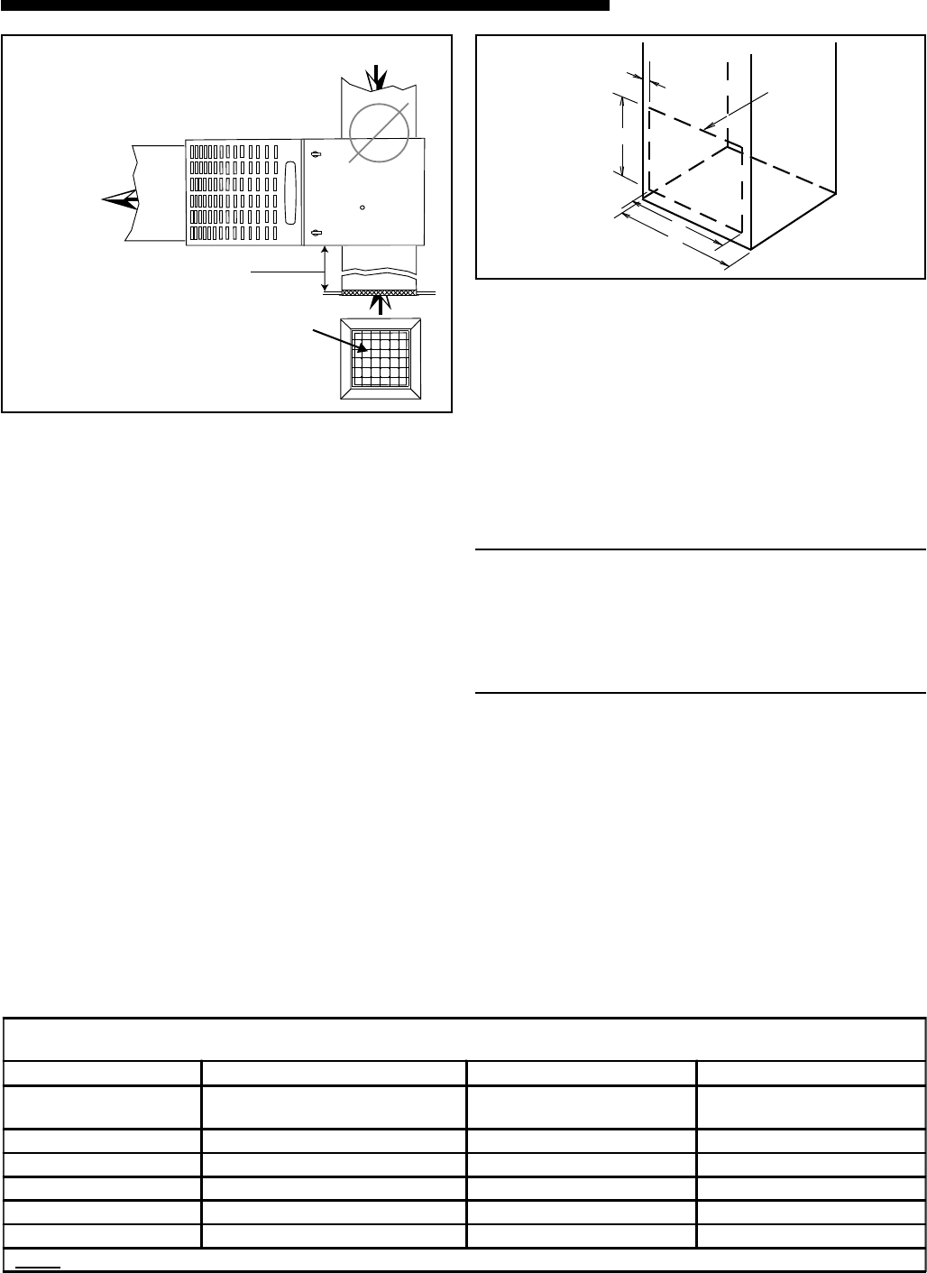
FILTER
REMOVE FILTER FROM UPFLOW
FURNACE WHEN RETURN DUCT IS
ATTACHED TO FURNACE TOP SIDE
(HORIZONTAL LEFT OR RIGHT
APPLICATIONS) AS SHOWN.
Close coupled (less than 36")
return (filter directly beneath bottom
side return) not recommended due to
noise considerations. If used, securely
attach 1/2" mesh metal hardware cloth
protective screen to the inside bottom of
filter grill.
q
*
SEE OUTLINE DRAWING
w
LOCATING
NOTCHES
PROVIDED
FOR SIDE
RETURN
CUTOUT
*
*
*
*
CUT OUT
FOR
SIDE
FILTER
FRONT
of Furnace
7. Connect the duct work to the furnace. See Outline
Drawing (pages 4&5) for supply and return duct size
and location. Flexible duct connectors are recom-
mended to connect both supply and return air ducts
to the furnace.
If only the front of the furnace is accessible, it is
recommended that both supply and return air
plenums are removable.
8. When replacing a furnace, old duct work should be
cleaned out. Thin cloths should be placed over the
registers and the furnace fan should be run for
10 minutes. Don’t forget to remove the cloths
before you start the furnace.
RETURN AIR FILTERS
(Filter and filter rack are not supplied with unit)
TYPICAL UPFLOW RETURN AIR FILTER INSTALLA-
TIONS
These furnaces require high velocity type air filters.
The optional filters may be located within the furnace
blower compartment for UPFLOW furnaces in either a
BOTTOM or SIDE (left side or right side) return air
inlet. Some optional filters may need to be trimmed for
side or bottom filter use.
NOTE:
On upflow 5 or 6 ton airflow models where the
airflow requirement exceeds 1800 CFM - Models will
require return air openings and filters on: (1) both
sides; or (2) one side and the bottom; or (3) just the
bottom.
The furnace and the blower filter rack installation can
be seen in Figure 13.
The optional furnace filter in the bottom or side con-
figuration can be removed by simply turning the two
latches on the blower door and tilting the door forward.
The filter rails are spring loaded for automatic adjust-
ment to allow standard size, locally obtainable replace-
ment filters. The filter rack itself slides to adjust to the
required width needed for bottom or side return.
MINIMUM CLEARANCE FROM COMBUSTIBLE MATERIALS FOR
UPFLOW/HORIZONTAL AND DOWNFLOW/ HORIZONTAL FURNACES
UNIT LOCATION
FURNACE SURFACE
VERTICAL
CLOSET
HORIZONTAL
CLOSET
HORIZONTAL
ALCOVE / ATTIC
SIDES 0" 1" 0"
BACK 0" 3" 6"
TOP 1" 1" 1"
FRONT 3" 3" 18"
VENT 0" 0" 0"
NOTE
: CLEARANCE REQUIRED AT TOP OF PLENUM IS 1"


