


14 18-CD19D6-32
Installer’s Guide
REAR
SIDE
CUT-OUT
ALTERNATE FILTER
CLIPS LOCATION
Airflow
Airflow
d
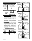
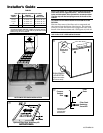
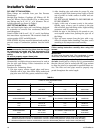
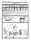
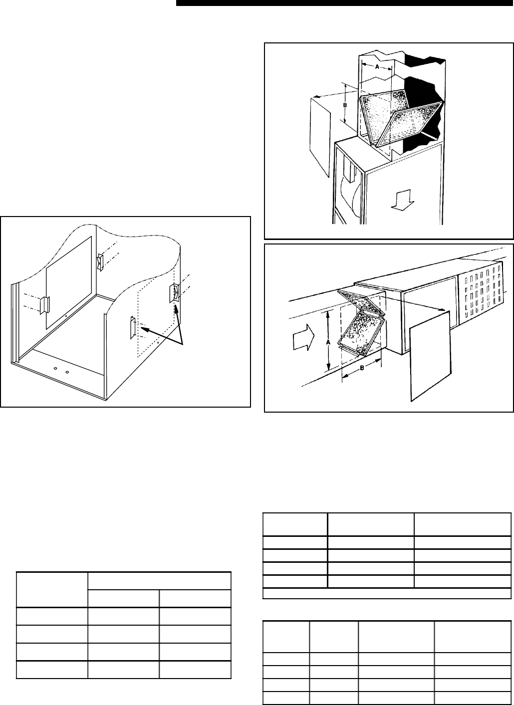
Two high velocity type air filters are required for each down-
flow furnace. Downflow furnace filters must be located
outside the furnace cabinet. Typical installations are shown
in Figures 23 and 24. Tables 7 and 8 (page 13) provide
information for installation of the filter retaining brackets
shipped with downflow furnaces.
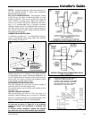
f
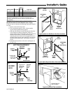
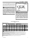
Optional horizontal filter conversion kits are BAYFLTR203
for 17 1/2" width cabinets, BAYFLTR204 for 21" width
cabinets, and BAYFLTR205 for 24" width cabinets. These
include filters and brackets necessary for horizontal filters.
In addition, optional door kit BAYFLTR206 is also available.
See Figures 21 and 24.
i
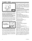
RETURN AIR FILTERS FOR UPFLOW FURNACE
IN HORIZONTAL CONFIGURATION
When the Upflow Furnace is installed in a horizontal configu-
ration, the filter must never be installed inside or outside the
cabinet directly above the blower assembly. See Figure 11
(page 9). Remote filter grilles may be used for homeowner
convenience or the filters may be installed in the duct work
upstream of the furnace. See Figures 11 (page 9) and 21 (page
11).
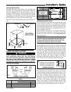
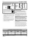
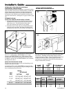
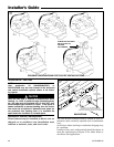
ALTERNATE UPFLOW
FILTER CLIP / BRACKET INSTALLATION - KIT09224
1. Determine the location to be used. The furnace cabinet
has dimples for location of the alternate furnace clips
(Side return only). Pre-drill clearance holes with a
3/16" drill. Bottom return holes are pre-drilled.
2. Install the clips in front and rear of the desired location
using the screws provided. The filter clip with the leaf
spring mounts in the rear of the cabinet. See Figure 22.
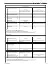
s
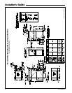
UNIT
SIZE
RETURN AIR
BOTTOM SIDE
14-1/2" CUT ON LINE DO NOT CUT
17-1/2" DO NOT CUT DO NOT CUT
21" DO NOT CUT CUT ON LINE
24-1/2" DO NOT CUT CUT ON LINE
TABLE 6
INSTALLING THE OPTIONAL FILTER
The filter may need to be cut to fit the unit depending on the
location of the return air filter.
A score line and the words “CUT HERE” are located on the
end of the filter. If your application requires cutting the filter,
do so as indicted by the score mark.
TYPICAL DOWNFLOW FURNACE
RETURN AIR FILTER INSTALLATIONS
TABLE 7
TABLE 8
CABINET
WIDTH
RETURN
DUCT
WIDTH
FILTER ACCESS
OPENING -
DIMENSION "A"
FILTER ACCESS
OPENING -
DIMENSION "B"
14-1/2" 13-1/4" 12" 14"
17-1/2" 16-1/4" 15" 14"
21" 19-3/4" 19-1/2" 14"
24-1/2" 23-1/4" 22" 14"
CABINET
WIDTH
FILTER
SIZE
FILTER BRACKET
LOCATION *
14-1/2" 2 - 14X20X1 12-7/8"
17-1/2" 2 - 16X20X1 14-3/8"
21" 2 - 16X20X1 13-1/8"
24-1/2" 2 - 16X20X1 11-5/8"
* Location dimension is from end of duct to the screw holes for the bracket.
Optional door kit
BAYFLTR206