


16 18-CD19D6-32
Installer’s Guide
PVC VENT FITTING MATERIAL
These fittings are available from your Gas Furnace
Distributors.
Straight Pipe Sections, Couplings, 45° Elbows, 60° El-
bows, 90° Elbows, Vent or Sanitary Tee, or other neces-
sary fittings may be 2", 2½", 3", or 4" diameter. The al-
lowable materials are shown in Table 8.
VENT FITTING MATERIAL – PLASTIC
Gas and liquid tight single wall vent fittings, designed
for resistance to corrosive flue condensate, MUST be
used throughout.
Listed in Table 10 & 11 are 2", 2½", 3", and 4" size fittings
that meet these requirements. The materials listed are
various grades of PVC and ABS plastic.
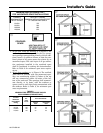
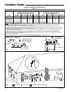
PIPE JOINTS: All joints must be fastened and sealed to
prevent escape of combustion products into the build-
ing.
NOTE:
It is recommended that the first joints from the furnace
be connected and sealed with high temperature RTV.
This will enable the pipes to be removed later without
cutting.
Be sure to properly support these joints.
BONDING OF PVC
Commercially available solvent cement must be used to
join the pipe and fittings. Follow instructions on the
container carefully.
Procedure for Cementing Joints:
1. Cut pipe square, remove ragged edges and burrs.
Chamfer end of pipe, then clean fitting socket and
pipe joint area of all dirt, grease, moisture or chips.
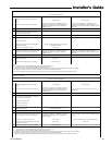
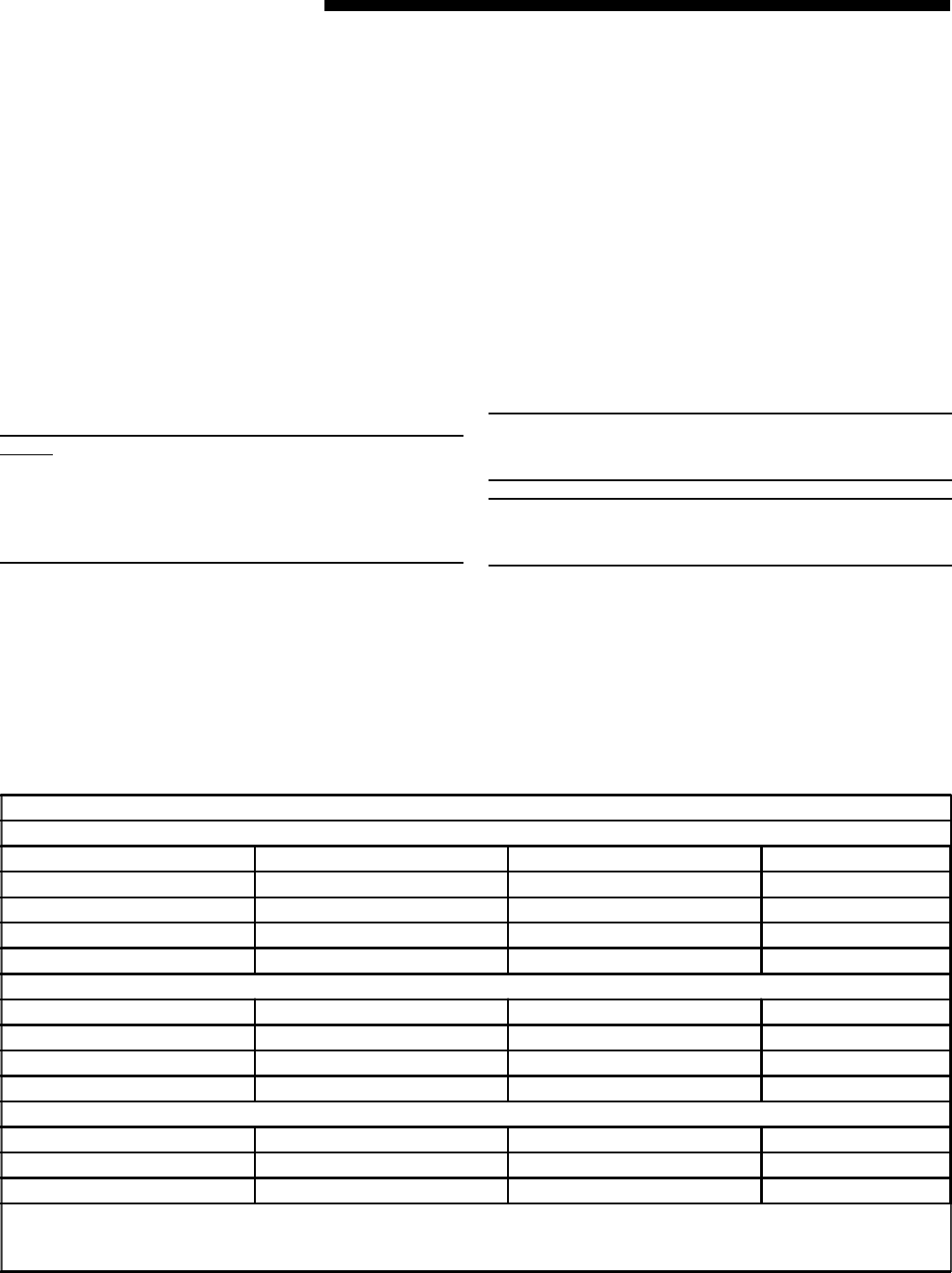
TABLE 9
PLASTIC PIPE DESIGNATIONS
PVC
ASTM STANDARD PIPE TYPE ALLOWABLE TEMPERATURE MARKING
F891 CELLULAR CORE *158 ASTM F891
D2665 DWV PIPE **158 ASTM D2665
D1785 SCH 40, 80, 120 **158 ASTM D1785
D2241 SDR SERIES **158 ASTM D2241
CPVC
ASTM STANDARD PIPE TYPE ALLOWABLE TEMPERATURE MARKING
D2846 CPVC 41 **212 ASTM D2846
F441 SCH 40, 80 **212 ASTM F441
F442 SDR SERIES **212 ASTM F442
ABS
ASTM STANDARD PIPE TYPE ALLOWABLE TEMPERATURE MARKING
D2661 SCH 40 DWV ***180 ASTM D2661
F628 SCH 40 DWV CELLULAR CORE ***180 ASTM F628
* - Allowable temperatures based on classifications covered in ASTM D4396 [Deflection Temps Under Load (264 PSI)]
** - Allowable temperatures based on classifications covered in ASTM D1784 [Deflection Temps Under Load (264 PSI)]
*** - Allowable temperatures based on classifications covered in ASTM D3965 [Deflection Temps Under Load (264 PSI)]
2. After checking pipe and socket for proper fit, wipe
socket and pipe with cleaner-primer. Apply a liberal
coat of primer to inside surface of socket and out-
side of pipe.
DO NOT ALLOW PRIMER TO DRY BEFORE AP-
PLYING CEMENT.
3. Apply a thin coat of cement evenly in the socket.
Quickly apply a heavy coat of cement to the pipe
end and insert pipe into fitting with a slight twisting
movement until it bottoms out.
4. Hold the pipe in the fitting for 30 seconds to pre-
vent tapered socket from pushing the pipe out of
the fitting.
5. Wipe all excess cement from the joint with a rag.
Allow 15 minutes before handling. Cure time varies
according to fit, temperature and humidity.
NOTE:
Follow venting instructions carefully when using PVC
cement.
IMPORTANT:
All joints must be water tight. Flue condensate is some-
what acidic, and leaks can cause equipment damage.
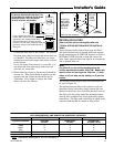
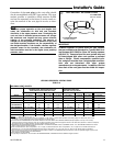
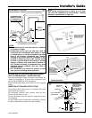
Connection of the pipe and collar of the combustion
air inlet should just be a friction fit. It is recommended
that the inlet air joint be sealed with RTV type sealant
to allow the joint to be separated for possible future ser-
vice. The inlet and vent pipes must be properly sup-
ported throughout the entire length.