


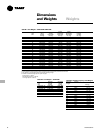


Mechanical
Specifications Options
PKG-PRC002-EN 99
Waterside Economizer Flow Control
Units equipped with a waterside
economizer can be set from the human
interface panel for variable or constant
water flow.
• Constant Water Flow
Two-way modulating control shutoff
valves are wired, controlled, and installed
in the unit. One valve is located in the
economizer’s water inlet, and the other is
in the condenser bypass water inlet.
When the waterside economizer enables,
the two-way valve modulates to maintain
the discharge air temperature setpoint.
As the economizer valve opens, the
condenser bypass valve closes, and vice
versa. Full water flow is always
maintained through the condensers. Both
valves will close in the event of a power
failure.
• Variable Water Flow
Two-way modulating control shutoff
valves are wired, controlled, and installed
in the unit. One valve is located in the
economizer’s water inlet, and the other is
in the condenser bypass water inlet.
When the economizer valve is active, the
condenser bypass valve closes. The
economizer valve modulates, thus water
flow through the unit modulates. If the
water is cool enough for economizing, but
mechanical cooling is also required, the
economizer valve fully opens to establish
full water flow through the condensers.
Whenever the water is too warm for
economizing and there is a call for
cooling, the economizer valve fully closes
and the bypass valve fully opens,
establishing full water flow through the
condensers. Full water flow is always
maintained through the condensers
when mechanical cooling is required.
Both valves close whenever cooling is
not required and in the event of a power
failure.
Water Flow Switch
A water flow switch is factory installed in
the condenser water pipe within the unit.
Whenever the flow switch detects a
water flow loss prior to or during
mechanical cooling, compressor
operation locks out and a diagnostic code
displays. If water flow is restored, the
compressor operation automatically
restores.
Service Valves
Service valves are factory installed on
each circuit before and after the
compressor to allow compressor
isolation for servicing.
Heating Coils
• Electric Heat
A single stage electric heating coil and
controls are factory installed inside the
unit casing at the fan discharge. An open
construction type coil is provided. Power
to the electric heater is factory wired to
the unit’s single-point power connection.
• Hot Water
The hot water heating assembly includes
the coil and filter section and is factory
installed on the unit’s inlet. A three-way
modulating valve, actuator, manifold
piping, and automatic air vent are also
factory installed. The coil is a Trane type
WC, constructed of
5
/
8
-inch (16 mm) OD
copper tubes arranged in a parallel
pattern. The copper tubes are expanded
into aluminum fins positioned
continuously across the entire coil width,
not exceeding 12 fins per inch. The coil
casing is 16-gauge steel. Coil
performance is rated at a maximum
working pressure of 200 psig in
accordance with ARI Standard 410.
Supply and return water header
connections are female tapered NPT and
are accessed from the unit’s left side.
• Steam
The steam heating assembly includes the
coil and filter section, factory installed on
the unit’s inlet. A two-way modulating
valve, actuator, and manifold piping are
also factory installed. Also, connections
are provided for field installing a vacuum
breaker. The coil is a Trane type NS,
constructed of one inch (25 mm) OD
copper tubes arranged in a parallel
pattern. The copper tubes are expanded
into aluminum fins positioned
continuously across the entire coil width,
not exceeding 42 fins per foot. The coil
casing is 16-gauge steel. Coil
performance is rated at a maximum
working pressure of 100 psig in
accordance with ARI Standard 410.
Supply and return steam header
connections are female tapered NPT and
are accessed from the unit’s left side.
Factory provided controls limit the steam
coil leaving air temperature to no more
than 105 F (41 C) at all operating
conditions.
Single Stage Electric Heat Interface
A heat control module will be factory
installed and wired for customer supplied
and powered electric heat. This module
will allow the unit to stage the customer-
provided electric heat. Single stage
electric heat control will be accomplished
with one dry binary output rated at one
amp for 115 VAC.
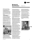
Hydronic Heating Control Interface
A heat control module will be factory
installed and wired for customer supplied
hydronic heating. This control will be
accomplished with a dry binary output, 0-
10 VDC analog control signal.
Time Clock
A factory-installed programmable time
clock is wired to the unoccupied mode
binary input to provide on/off control. The
timer is accessible without opening the
control panel door, and is a seven-day
type with a maximum of four operations
per day. A permanent built-in
rechargeable battery pack is provided.
Low Entering Air Temperature Protection
Device
A thermostat limit switch is factory
mounted on the unit’s entering air side
with a capillary tube serpentine across
the coil face. If the temperature falls
below 35 F (2 C), the fan shuts down and
the waterside economizer and/or
hydronic heat valve option opens to allow
full water flow. The heat output also
energizes. A manual reset is required.
Note: this option is standard on units with
a waterside economizer or hydronic
heat.
Non-fused Disconnect Switch
The unit has a factory mounted non-fused
disconnect switch accessible without
opening the control panel door.
Dual Point Power Terminal Blocks
Two separate power terminal blocks are
available to bring power to the unit; one
terminal block provides power to the
compressors and the other provides
power to the fan motor and controls.
Note: a single point power terminal block
is standard.