


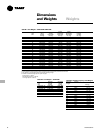


Mechanical
Specifications
PKG-PRC002-EN 95
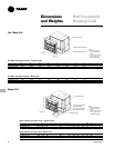
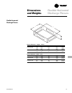
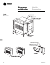
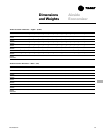
Signature Series Self-
Contained Units
Cabinet
The unit framework shall be formed
structural steel members of 14-gauge
galvanized steel. Exterior panels shall be
fabricated from 18-gauge galvanized
steel. The fan and compressor sections
shall be insulated with ¾-inch (19 mm) of
1.75 lb./cu. ft. (28 kg./cu. ft.) density
fiberglass insulation.
The unit shall be provided with removable
panels to allow service access to
compressors, condensers, fan motor, fan
bearings, coils, and valves. Removable
panels shall be secured with quick-acting
fasteners. The refrigerant sight glasses
shall be accessible during operation. The
control panel door shall have lift-off
hinges.
Compressors
Units shall have multiple compressors
with independent circuits for water-cooled
units and manifolded circuits for air-
cooled units. Compressors shall be
manufactured by the unit manufacturer.
Scroll compressors shall be heavy duty
suction cooled type with suction screen,
centrifugal oil pump with dirt separator, oil
charging valve, and oil sight glass.
Protective devices for low pressure, high
pressure, and motor temperature shall be
provided. The compressors shall be
mounted on isolators for vibration
isolation.
Condenser (SCWF/SIWF only)
One condenser shall be provided for each
compressor. The condensers shall be
shell-and-tube design with removable
heads and mechanically cleanable tubes.
Tubes shall be ¾-inch (19mm) OD and
constructed of copper. Condenser
waterside working pressure shall be 400
psig. All condenser water piping including,
cleanouts, shall be factory installed to
provide single connections for water inlet
and outlet.
Evaporator
The evaporator coil shall be seamless
copper tubes expanded into aluminum
fins. Tubes shall be ½-inch (13mm) OD
with internally enhanced surfaces. Coil
shall have staggered tube arrangement
with intertwined circuiting and no more
than 12 fins per inch.
The drain pan shall be positively sloped in
all directions to ensure proper condensate
removal. The drain pan shall be fabricated
of galvanized steel and insulated with ¾-
inch (19 mm) of 1-lb. (0.5 kg) density
fiberglass. Drain piping, including a trap
with cleanout, shall be provided with a
single-point connection to the unit’s
exterior.
Refrigerant Circuit (SCWF only)
Refrigerant circuits shall be independent
and completely piped including sight
glasses, distributors, thermal expansion
valves with adjustable superheat and
external equalizer, and high pressure
relief valves with ½-inch (13 mm) flare
connection. Filter driers ship loose for field
installation. Unit shall be provided with
adequate means of frost control. The
circuits shall be factory dehydrated,
charged with oil and refrigerant 22.
Compressors shall be mounted on
rubber-in-shear isolators for vibration
isolation.
Refrigerant Circuit (SCRF/SIRF only)
Two refrigerant circuits shall be piped to
the unit’s exterior. The refrigerant piping
includes filter driers (for field installation),
sight glasses, distributors, thermal
expansion valves with adjustable
superheat and external equalizer. Unit
shall be provided with adequate means of
frost control. The circuits shall be factory
tested, dehydrated and then charged with
dry nitrogen. Compressors shall be
mounted on rubber-in-shear isolators for
vibration isolation.
Supply Fan
The supply fan shall be a single forward
curved medium pressure fan secured to a
solid steel shaft with grease lubricated
bearings designed for 200,000 hours.
Both fan bearings shall have greaselines
extended to a common location. The drive
components shall include fixed pitch
sheaves and multiple V-belt sized for
130% nominal motor horsepower. The
supply fan motor shall have a service
factor of 1.15. The supply fan motor shall
be either:
• Standard efficiency open drip-proof
• Premium efficiency open drip-proof
• Totally enclosed fan cooled standard
efficiency.
Supply fan motor shall have a standard T-
frame. All drive components shall be
accessible without using scaffolds or
ladders.
The entire fan assembly, including drive
components, shall be mounted on a
common base. The fan base shall be
isolated inside the unit. The entire
assembly shall be statically and
dynamically balanced at the factory.
Filters
Two-inch (51 mm) throwaway fiberglass
filters shall be provided for installation
during construction.
Unit Controls - DDC
Microprocessor controls shall be provided
to control all unit functions. The control
system shall be suitable to control CV or
VAV applications. The controls shall be
factory-installed and mounted in the main
control panel. All factory-installed controls
shall be fully commissioned (run tested) at
the factory. The unit shall have a human
interface panel with 16-key keypad, a
two line, 40 character clear language
(English, French, or Spanish) display as
standard to provide the operator with full
adjustment and display of control data
functions. The unit controls shall be used
as a stand-alone controller or as part of a
building management system involving
multiple units.
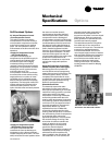
The unit shall be equipped with a
complete microprocessor control system.
This system shall consist of temperature
and pressure (thermistor and static
pressure transducer) sensors, printed
circuit boards (modules) and a unit
mounted human interface panel. Modules
(boards) shall be individually replaceable
for service ease. All microprocessors,
boards, and sensors shall be factory
mounted, wired, and tested.
The microprocessor boards shall be
stand-alone DDC controls not dependent
on communications with an on-site PC or
building management network. The
microprocessors shall be equipped with
on-board diagnostics, indicating that all
hardware, software, and interconnecting
wiring are in proper operating condition.
The modules (boards) shall be protected
to prevent RFI and voltage transients
from affecting the board’s circuits. All field
Self-Contained