


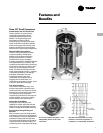

Model Number
Description
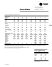
PKG-PRC002-EN 15
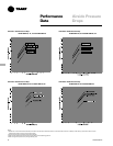
Selection
Procedure
Digit 25 - Industrial Options
A = Protective Coating Evaporator Coil
B = Silver Solder
C = Stainless Steel Screws
D = A and B
E = A and C
F = B and C
G = A, B, and C
0 = None
Digit 26 - Drain Pan Type
A = Galvanized Sloped
B = Stainless Steel Sloped
Digit 27 - Waterside Economizer
A = Mechanical Clean Full Capacity (4-row)
B = Mechanical Clean Low Capacity (2-row)
C = Chemical Clean Full Capacity (4-row)
D = Chemical Clean Low Capacity (2-row)
0 = None
Digit 28 - Ventilation Control
B = Airside Econ w/ Traq
™
Damper
(Top O/A)
C = Airside Econ w/ Standard
Damper (Top O/A)
E = Airside Econ w/ Traq
™
Damper and
Comparative Enthalpy
(Top O/A)
F = Airside Econ w/ Standard Damper and
Comparative Enthalpy (Top O/A)
H = None, 2-Position Damper Ventilation
Interface
J = Airside Economizer Interface
K = Airside Economizer Interface w/
Comparative Enthalpy
Digit 29 - Water Piping
D = Left Hand Basic Piping
F = Left Hand Intermediate Piping
K = Left Hand Basic w/ Flow Switch
M = Left Hand Intermediate
w/ Flow Switch
0 = None
Digit 30 - Condenser Tube Type
A = Standard Condenser Tubes
B = 90/10 CuNi Condenser Tubes
0 = None (Air-cooled Only)
Digit 31 - Compressor Service Valves
1 = With Service Valves
0 = None
Digit 32 - Miscellaneous System Control
1 = Timeclock
2 = Interface for Remote HI (IPCB)
3 = Dirty Filter Switch
4 = 1 and 2
5 = 1 and 3
6 = 2 and 3
7 = 1, 2 and 3
0 = None
Digit 33 - Control Interface Options
A = Generic BAS Module (GBAS)
B = Ventilation Override Module
(VOM)
C = Tracer Comm. Interface Module
(TCI)
D = Remote Human Interface (RHI)
E = GBAS and TCI
F = VOM and TCI
G = GBAS and VOM
H = GBAS and RHI
J = VOM and RHI
K = TCI and RHI
L = GBAS, VOM, and TCI
M = GBAS, VOM, and RHI
N = GBAS, TCI, and RHI
P = VOM, TCI, and RHI
R = GBAS, VOM, TCI, and RHI
0 = None
Digit 34 - Agency
T = UL Agency Listing
0 = None
Digit 35 - Filter Type
1 = Construction Throwaway
2 = Med Eff. Throwaway
Digit 36 - Miscellaneous Control Option
A = Low Entering Air Temp. Protect
Device (LEATPD)
B = High Duct Temp T-Stat
(Ship Separate)
C = Plenum High Static Switch
(Ship Separate)
E = A and B
F = A and C
H = B and C
L = A, B, and C
0 = None
Self-Contained Model Number Continued —
P S W F S A 1 1 0 AO
1 2 3 4 5 6 7 8 9 10 11
Self-Contained Accessory Model Number Description
Digit 1 - Parts/Accessories
P = Parts/Accessories
Digit 2 - Unit Model
S= Self-Contained
Digit 3 - Shipment
W = With Unit
Digit 4 - Development Sequence
F = Signature Series
G = Modular Series
Digit 5 - Sensors and Other Accessories
S = Sensors
Digit 6 - Sensors (Field Installed)
A = BAYSENS017 - Zone Temp Only (CV
and VAV)
B = BAYSENS013 - Zone Temp with
Timed Override Button (CV and VAV)
C = BAYSENS014 - Zone Temp with
Timed Override Button, Setpoint Dial
(CV and VAV)
E = BAYSENS008 - CV Zone Sensor
F = BAYSENS010 - CV Zone Sensor with
Indicator Lights
G = BAYSENS019 - CV Programmable
Night Setback Sensor
H = BAYSENS021 - VAV Zone Sensor
with Indicator Lights
J = BAYSENS020 - VAV Programmable
Night Setback Sensor
K = Remote Sensor Kit
L = Outside Air Temperature Sensor Kit
M = Outside Air Humidity Sensor Kit
0 = None
Digit 7 - Low Entering Air Temperature
Protection Device (Field Installed)
1 = Low Entering Air Tempeature
Protection Device
0 = None
Digit 8 - Carbon Dioxide Sensor (field
installed)
1 = Carbon Dioxide Sensor Kit
0 = None
Digit 9 - Not Used
0 = None
Digit 10, 11 - Design Sequence
A0 = A Design