


Performance Airside Pressure
Data Drops
PKG-PRC002-EN 23
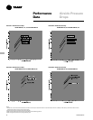
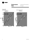
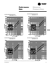
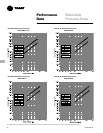
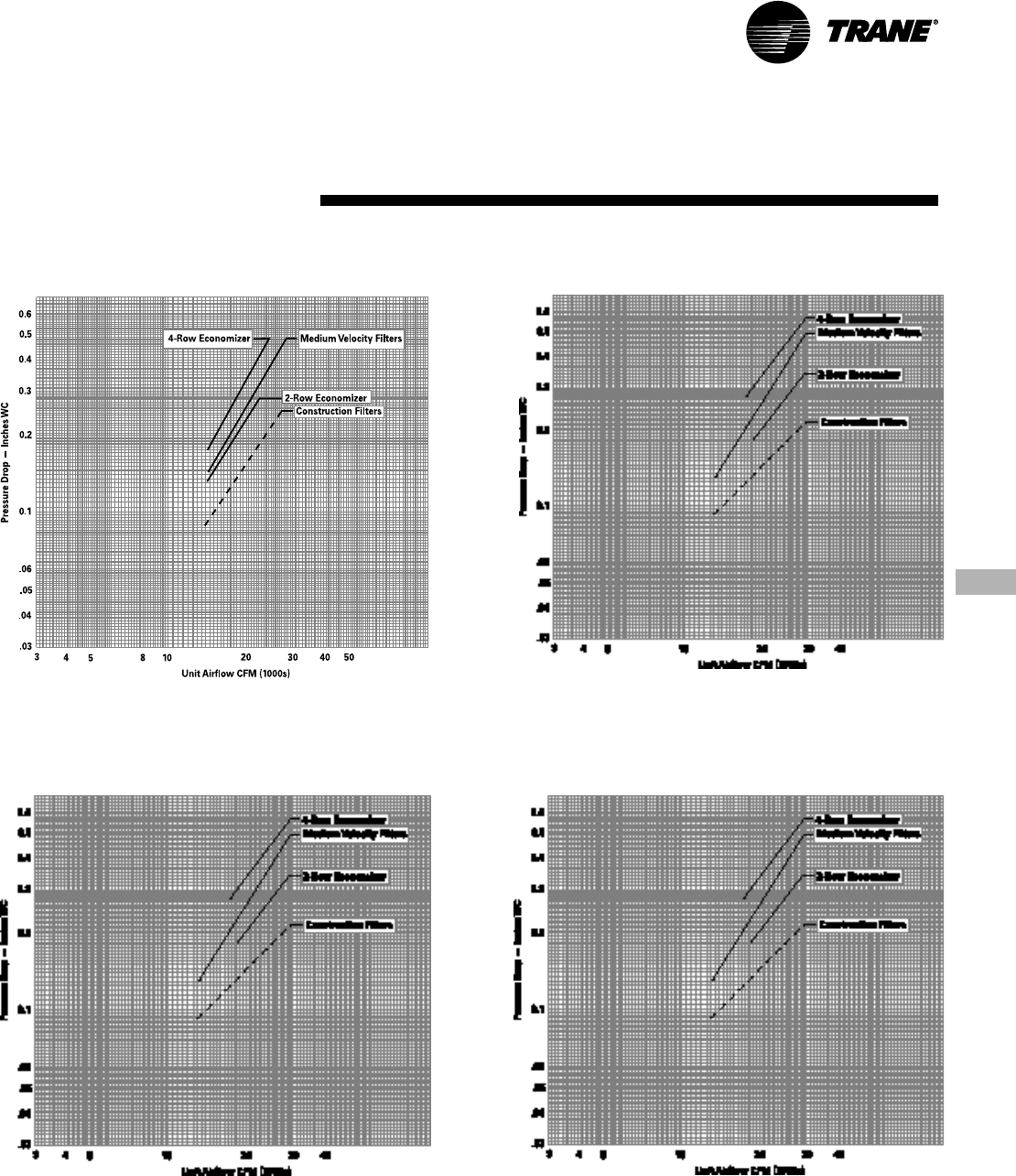
Chart PD-6. Airside Pressure Drop
SCWF/SIWF 65
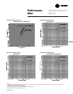
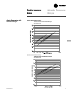
Chart PD-5. Airside Pressure Drop
SCWF/SIWF 52, 58 and SCRF/SIRF 50
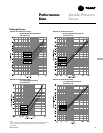
Chart PD-8. Airside Pressure Drop
SCWF/SIWF 80 and SCRF/SIRF 60
Chart PD-7. Airside Pressure Drop
SCWF/SIWF 72
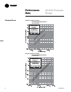
Notes:
1. Dotted line on construction filters indicates cfm where face velocity exceeds manufacturer’s recommended maximum of 300 fpm. After startup, construction filters must be
replaced with medium velocity or high velocity filters.
2. Air pressure drop through electric heat is 0.5 inches WC.
3. Refer to Page 25-26 for pressure drop through flexible horizontal discharge plenum.
4. Refer to Page 24 for pressure drop through heating coils.