


SCXG-SVX01B-EN 83
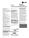
Table O-GI-6. GBAS Analog Input Setpoints
Control Parameter Signal Range Setpoint Range
Occupied Zone Cooling Setpoint 0.5 to 4.5 vdc 50 to 90 F
(CV units only)
Unoccupied Zone Cooling Setpoint 0.5 to 4.5 vdc 50 to 90 F
(CV and VAV)
Occupied Zone Heating Setpoint 0.5 to 4.5 vdc 50 to 90 F
(CV units only)
Unoccupied Zone Heating Setpoint 0.5 to 4.5 vdc 50 to 90 F
(CV and VAV)
Supply Air Cooling Setpoint 0.5 to 4.5 vdc 40 to 90 F
(VAV units only)
Supply Air Hydronic Heating Setpoint 0.5 to 4.5 vdc 40 to 180 F
(VAV units only)
Space Static Pressure Setpoint 0.5 to 4.5 vdc 0.03 to 0.30 IWC
Supply Air Pressure Setpoint 0.5 to 4.5 vdc 0.0 to 5.0 IWC
(VAV units only)
Note: 1. Input voltages less than 0.5 vdc are considered as 0.5 vdc input signal is lost, the setpoint will
“clamp” to the low end of the setpoint scale. No diagnostic will result from this condition.
2. Input voltages greater than 4.5 vdc are considered to be 4.5 vdc.
3. The actual measured voltage is displayed at the HI.
Table O-GI-7. GBAS Input Voltage Corresponding Setpoints
Volts Temp. Volts Temp. Volts Temp Volts Temp
(F) (F) (F) (F)
0.5 50 1.6 60 2.6 70 2.7 80
0.6 51 1.7 61 2.7 71 2.8 81
0.7 52 1.8 62 2.8 72 2.9 82
0.8 53 1.9 63 2.9 73 3.0 83
0.9 54 2.0 64 3.0 74 3.1 84
1.0 55 2.1 65 3.1 75 3.2 85
1.1 56 2.2 66 3.2 76 3.3 86
1.2 57 2.3 67 3.3 77 3.4 87
1.3 58 2.4 68 3.4 78 3.5 88
1.5 59 2.5 69 3.5 79 3.6 89
Owner
General
Information