


SCXG-SVX01B-EN 37
Electrical
Requirements
Unit Wiring Diagrams
Specific unit wiring diagrams are
provided on the inside of the control
panel door. Use these diagrams for
connections or trouble analysis.
Supply Power Wiring
It is the installer’s responsibility to provide
power supply wiring to the unit terminal
block or the non-fused disconnect switch
option. Wiring should conform to NEC and
all applicable code requirements.
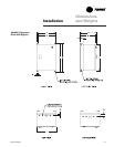
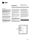
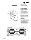
Bring supply wiring through the knockout
in the lower left side of the unit control
panel. Connect the three phase wires to
the power terminal block or the non-
fused disconnect switch in the control box
terminals. Refer to specific wiring
diagrams and fuse information in the
unit’s control panel.
Disconnect electrical power
source to prevent injury or death
from electrical shock.
Use only copper conductors for
electrical unit connections to
prevent equipment damage.
Correct phase sequence is
critical. If phase sequence of the
incoming line voltage is not
correct, it may result in motor
damage.
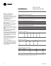
Voltage Range
Voltages must be within +- 10% the
nameplate voltage. Ensure the unit
voltage is balanced by measuring at the
compressor terminals. Voltage imbalance
on three phase systems can cause motor
overheating and premature failure.
Maximum allowable imbalance is 2.0
percent.
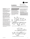
Voltage Imbalance
Read the voltage at the compressor
terminals to determine if it is balanced.
Voltage imbalance on three phase
systems can cause motor overheating
and premature failure. The maximum
allowable imbalance is 2.0%. Voltage
imbalance is defined as 100 times the
sum of the deviation of the three voltages
from the average (without regard to sign)
divided by the average voltage. For
example, if the three measured voltages
are 221, 230, and 227, the average
voltage would be:
(221 + 230 + 227) = 226 volts
3
The percentage of voltage imbalance is
then:
100 *
(226-221) = 2.2%
226
Control Power
In this example, 2.2% imbalance is not
acceptable. Whenever a voltage
imbalance of more than 2.0% exists,
check the voltage at the unit disconnect
switch. If the imbalance at the unit
disconnect switch does not exceed 2.0%,
faulty unit wiring is causing the
imbalance. Conduct a thorough
inspection of the unit electrical wiring
connections to locate the fault, and make
any repairs necessary.
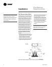
Access the connection terminal block
through the control panel on the unit’s
upper left side. All wiring should conform
to NEC and applicable local code
requirements.
Be sure all wiring connections are secure.
Reference the unit specific diagrams
inside the control panel.
Unit transformers are sized to
provide power to the unit only.
Do not use these transformers to
supply power to field equipment.
Field connections to these
transformers may create
immediate or premature
component failures.
ƽƽ
ƽƽ
ƽ
CAUTION
!
ƽƽ
ƽƽ
ƽ
CAUTION
!
ƽƽ
ƽƽ
ƽ
CAUTION
!
ƽƽ
ƽƽ
ƽ
CAUTION
!
Installation