


SCXG-SVX01B-EN 11
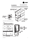
denser and fan motor access panels are
secured with quick-acting fasteners.
Access panels for evaporator coils,
expansion and water valves, and left fan
bearing are sheet metal screws. Access
to other components for service requires
removal of panels secured with sheet
metal screws. During operation, sight
glasses are viewable through portholes
on the upper right side panel of the fan
section.
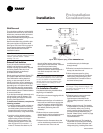
Disconnect electrical power
source before servicing the unit.
Failure to do so may result in
injury or death from electrical
shock or entanglement in moving
parts.
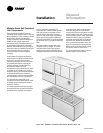
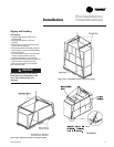
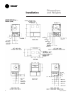
Service Access
See Figure I-PC-4 and Table I-PC-1 for
recommended service and code
clearances. Access to thermostat unit
controls is through a hinged access panel
door on the front, lower left of the unit’s
compressor section.
IntelliPak
®
unit control access is through a
panel on the middle right of the fan
section. The panel is secured with an
automatic latch and quick-acting fasten-
ers, which require a screwdriver to open.
Removable front unit panels provide
access to compressors, fan, motor, inlet
guide-vane actuator, and belts.
Removable left side panels give access to
drive side, fan bearing, inlet guide-vanes,
condensers, and waterside economizer
control valve. The compressor, con-
ƽƽ
ƽƽ
ƽ
WARNING
!
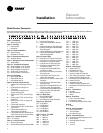
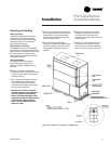
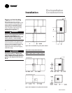
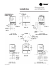
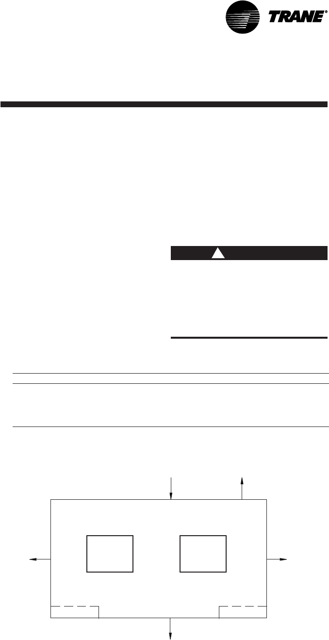
Figure I-PC-4. Top view of self-contained unit showing recommended service and code
clearances.
Pre-Installation
Considerations
Installation
Table I-PC-1. SCWG/SIWG/SCRG/SIRG Clearance Requirements
Side Distance Purpose
Front 42 in. (1066 mm) NEC code requirement
Left 18 in. Air-cooled units only
36 in. (914 mm) Refrigeration and waterside component service
77 in. Fan shaft removal
Right 36 in. (914 mm) Provides uniform airflow
Inlet 18 in. (457 mm) Provides uniform airflow
Air Inlet
18” (457.2 mm)
Minimum
See Table
42” (1066.8 mm)
Minimum
36” (914 mm)
Minimum