


48 SCXG-SVX01B-EN
Pre-Startup
Requirements
Airside Economizer Installation
Unit Handling
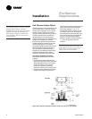
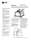
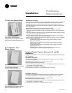
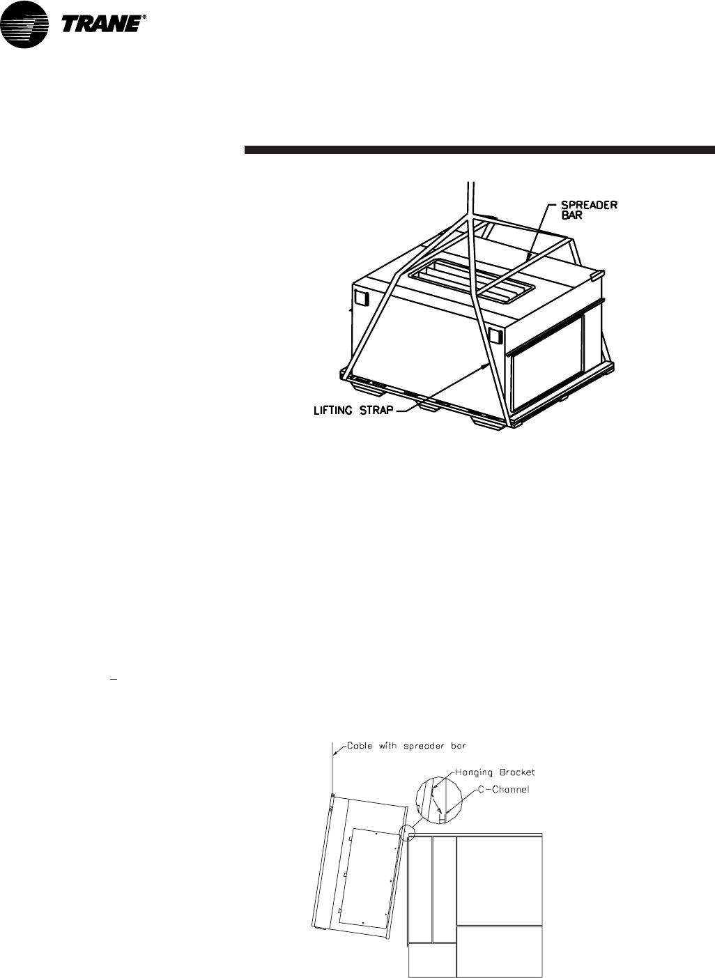
1. Hoist the damper cabinet to the
installation location with straps
positioned under the skid as shown in
Figure I-PR-12. Use spreader bars to
prevent unit damage during lifting.
2. With the damper cabinet at its final
location (near the unit), remove the
screws securing it to the skid from the
side flanges. Retain these screws for
later use.
Unit Preparation
3. The support legs are secured to the
skid, and the hanging bracket is secured
with wire ties to an inside flange near
the cabinet’s base. Remove the
C-channel collar and install it on the unit,
if not already installed.
4. Remove the roll of
1
/
8
” thick gasket
from the damper cabinet’s W-supports,
and apply it to the C-channel collar
mounted on the rear of the unit. This
gasket will provide a seal between the
damper cabinet and the unit.
5. Attach the legs (with screws provided)
to the leg brackets located on the
damper’s base.
6. Attach a field-provided clevis of
suitable strength (
>
1
/
2
” ), to each of the
corner lifting brackets through the
7
/
8
” diameter holes.
7. Attach to the clevises a means of lifting
the damper cabinet from its skid.
Unit Installation
8. Slowly raise the damper cabinet from
its skid.
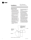
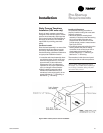
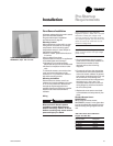
9. Attach the hanging bracket across the
front of the damper cabinet. Position it
with its short flange pointing to four
o’clock, and secure it with screws
provided. See Figure I-PR-13.
10. Lift the damper cabinet and position it
such that the hanging bracket is
positioned over the unit’s C-channel
collar.
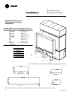
Figure I-PR-12. Proper lifting of the airside economizer.
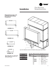
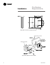
10. Lower the damper cabinet until the
holes in its side flanges are aligned with
the holes in the C-channel collar. Install
screws removed in step 3 through the
damper cabinet’s side flanges and into
the C-channel’s corresponding holes.
11. Attach ductwork to the top and back
dampers according to local codes.
Field Wiring Connections
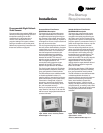
12. Open the damper cabinet’s door and
connect the factory-provided plug
from the actuator to the factory-
provided plug in the unit’s filter
section.
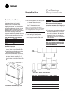
Figure I-PR-13. Proper installation of the airside economizer option.
Installation
13. Cabinets with TRAQ™ dampers
only: Unroll the two rolls of pneumatic
tubing located inside the damper
cabinet. Route these tubes through the
cabinet’s front upper panel (0.25 dia.
holes provided). Connect them to the
two pneumatic tubes protruding from
the customer electrical connection
panel on the unit. Be sure to connect like
tubes to each other (black to black,
white stripe to white stripe).
14. Cabinets with TRAQ™ dampers
only: Locate the “bullet” sensor and
rolled up wiring in the unit’s filter
section. Route it into the damper
cabinet and insert the sensor into the
sensor mounting clip attached to
underside of one of the Traq™
dampers.