


WSHP-SVX01D-EN 63
WARNING
Hazardous
Voltage!
Disconnect all electric power, in-
cluding remote disconnects be-
fore servicing. Follow proper
lockout/tagout procedures to en-
sure the power can not be inad-
vertently energized. Failure to
disconnect power before servic-
ing could result in death or seri-
ous injury.
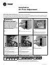
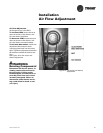
The following steps were sequenced
to aid in the installation and mating of
a waterside economizer to a water-
source heat pump (GEV and GEH 6
through 25 ton models).
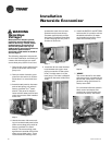
1 Remove the filter frame from the
unit.
2 Remove the waterside service
panel from the unit.
3 Remove the control box service
panel from the unit.
4 Remove the economizer and mis-
cellaneous mounting parts from
it’s packaging.
5 GEV ONLY: Mount the economiz-
er support angle (4475 1637 0100)
found in the economizer packag-
ing in the same holes of the re-
turn air filter frame removed in
step 1. The support angle screws
into the unit roof.
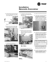
6 GEV ONLY: Hang the economizer
assembly from the economizer
support angle mounted in step 5.
7 Secure the economizer to the unit
using the four plates (4475 1630
0100) found in the economizer
packaging. Two plates should be
applied to each economizer side.
GEV ONLY: Secure the bracket on
the bottom of the economizer
cabinet to the unit compressor
compartment center post.
8 Install the field portion of the wa-
ter piping and the 3-way valve to-
gether.
9 VERIFY
The control board for the water-
side economizer is located at the
back of the control box. The tem-
perature rating of this board is
factory set to 55ºF.
10 Thread the economizer’s enter-
ing water temperature sensor
(4RT1) through the water-in line
of the water-source heat pump.
This sensor is used by the econo-
mizer’s 3-way valve to determine
if water flow should be directed
through the waterside economiz-
ing coil.
11 Tie wrap the thermistor to the
water line (supply side) upstream
of the water pipe to the econo-
mizer. The thermistor must be sit-
uated so that the thermistor is
capable of reading the actual en-
tering water temperature regard-
less of the economizer’s on or off
situation.
12 Insulate the thermistor with tub-
ing insulation.
13 Tie wrap each end of the tubing
insulation to prevent air filtration.
The tie wraps and insulation are
located in a baggie and shipped
inside of the unit.
14 Thread the factory wire harness
through the low voltage hole of
the heat pump to the 3-way
valve’s wire harness.
15 Connect the factory installed
wire harness to the to the wire
harness supplied with the 3-way
valve.
16 Bundle excess valve wire, and
wire tie the bundle neatly.
17 Install control side service panel
to the heat pump.
18 Install the unit filter frame to the
economizing inlet.
19 Insulate the economizing piping
package with field supplied pipe
insulation. Insulating the piping
will help stop condensation from
forming on the pipe.
Note: Trane does not provide
insulation on the economizing
piping package. This insulation
must be field provided and field
installed.
20 Install waterside service panel to
the heat pump.
21 Field pipe the drain lines of the
waterside economizer and water-
source heat pump together prior
to installing a condensate trap.
See page 51 for proper trapping
of condensation. The economizer
condensate line must be trapped
prior to the unit’s drain line. This
helps prevent air from being
sucked through the drain line
causing condensate to spit or
build-up in the economizer or
unit drain pans.
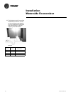
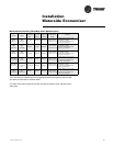
Actuator Wire #
Color
Factory Harness Wire #
Color
1 BLK = 25L-Black
2 WHT = 23T-White
3 WHT = 73A-White
Installation
Waterside Economizer