


56 WSHP-SVX01D-EN
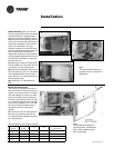
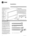
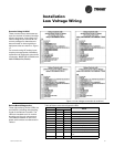
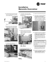
Thermostat Location
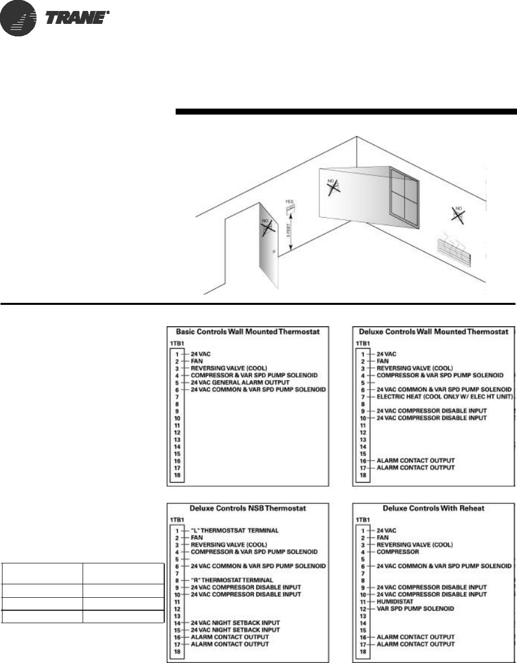
Location of the thermostat or zone
sensor is an important element of ef-
fective room control.
Areas where the thermostat or zone
sensor should not be located include:
Behind doors or corners; Near hot or
cold air ducts; Near radiant heat (heat
emitted from appliances or the sun);
Near concealed pipes or chimneys; On
outside walls or other non conditioned
surfaces; In air-flows from adjacent
zones or other units. See Figure 9 for
thermostat/sensor location.
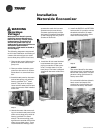
Controls Using 24 VAC
Before installing any wire, refer to the
electrical access locations on the unit
submittals located on page 10.
Ensure that the AC control wiring be-
tween the controls and the unit’s ter-
mination point does not exceed three
(3) ohms/conductor for the length of
the run.
Note: Resistance in excess of 3-ohms
per conductor may cause component
failure due to insufficient AC voltage
supply.
Check all loads and conductors for
grounds, shorts, and mis-wiring.
Use copper conductors unless other-
wise specified.
Do not run the AC low voltage wiring
in the same conduit with the high volt-
age power wiring.
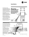
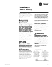
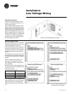
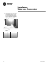
Low voltage connection diagrams for
basic and deluxe 24 volt control pack-
ages mounted on 1/2 through 5 ton
equipment sizes are shown in Figure
10.
Table 5: 24V AC conductors
Distance
from unit to Control
Recommended
Wire Size
000-460 feet 18 gauge
461-732 feet 16 gauge
733-1000 feet 14 gauge
Installation
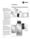
Low Voltage Wiring
Figure 9: Thermostat/sensor location
Figure 10: Low voltage connection (1/2
through 5 ton equipment)