


WSHP-SVX01D-EN 61
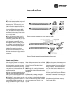
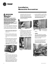
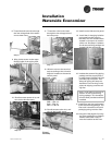
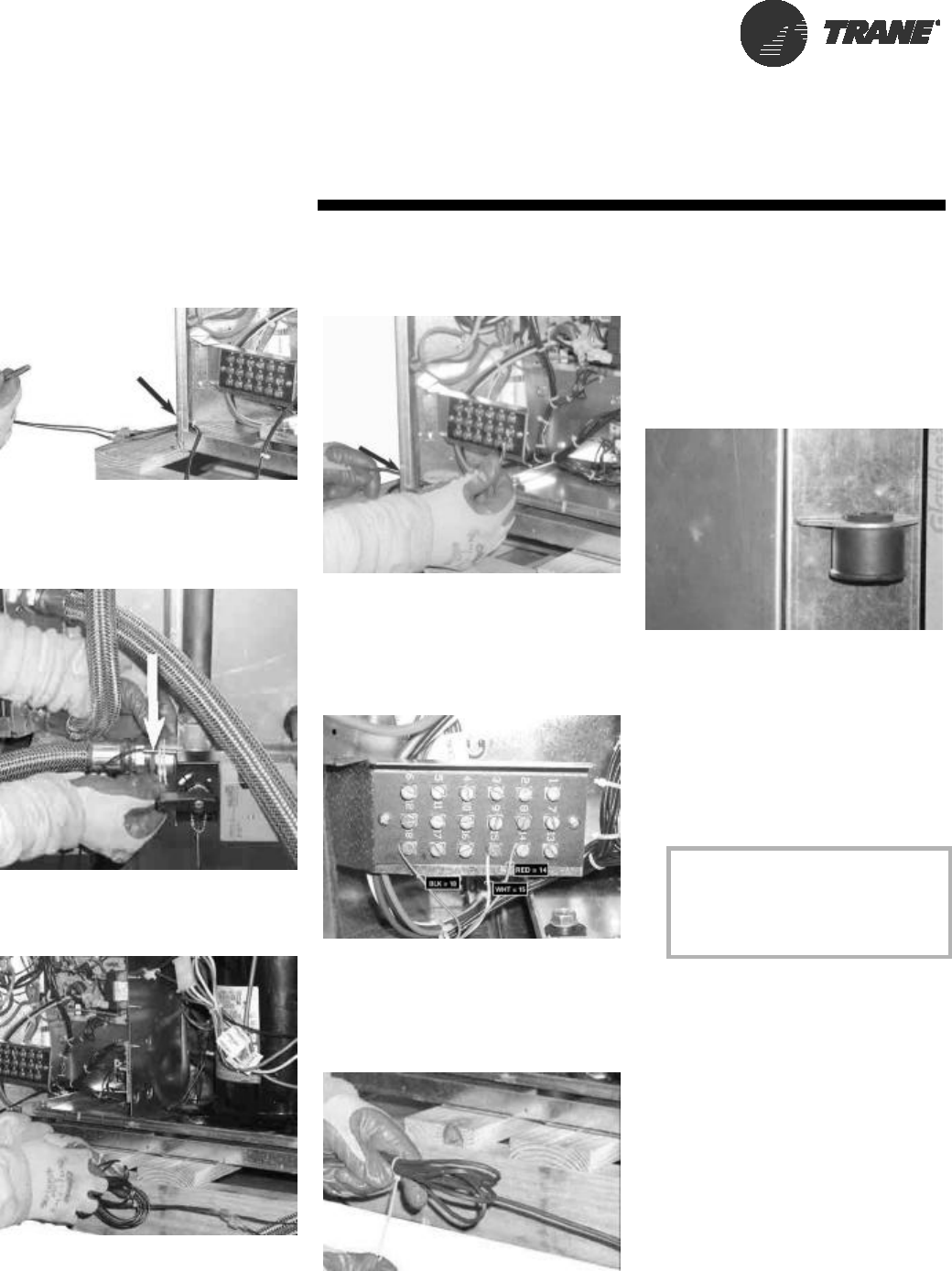
8 Thread the bulb and wire through
the low voltage hole of the water-
source heat pump.
Step 8
9 Wire-tie the sensor to the water
SUPPLY side of the piping (ON,
or BEFORE) the 2-position valve.
Step 9
10 Bundle excess sensor wire, and
wire tie the bundle neatly.
Step 10
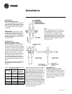
11 Thread the valve’s wire lead
through the low voltage hole of
the heat pump.
Step 11
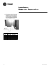
12 Wire the valve to the terminal
strip according to the unit wire
diagram located on the service
control panel.
RED = 1TB1-14
BLK = 1TB1-18
WHT = 1TB1-15
13 Bundle excess valve wire, and
wire tie the bundle neatly.
Step 13
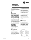
14 Install control side service panel.
15 Install the six hanging isolation
grommets into the hanging
brackets The unit isolators were
located in the return-air section
of the unit. See Step 2. Isolators
for the economizing package are
located with the economizer.
Step 15
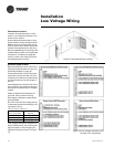
16 Insulate the economizing piping
package and the supply/return/
by-pass hoses (3-hoses) via field
provided pipe insulation. Insu-
lating the piping will stop con-
densation from forming on the
pipe and dripping onto the ceil-
ing tiles.
Note: Trane does not provide in-
sulation on the economizing
piping package. This insulation
must be field provided and field
installed.
17 Install filter rack (top and bottom)
to the economizing package. The
filter rack is located in the unit’s
packaging along with the filter.
18 Hang Unit. See page 51 for hang-
ing of the packaged unit. Bottom
screws referenced in step 4
must be installed at this time.
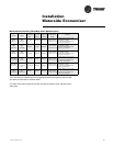
Installation
Waterside Economizer