


WSHP-SVX01D-EN 53
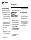
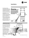
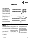
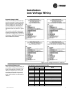
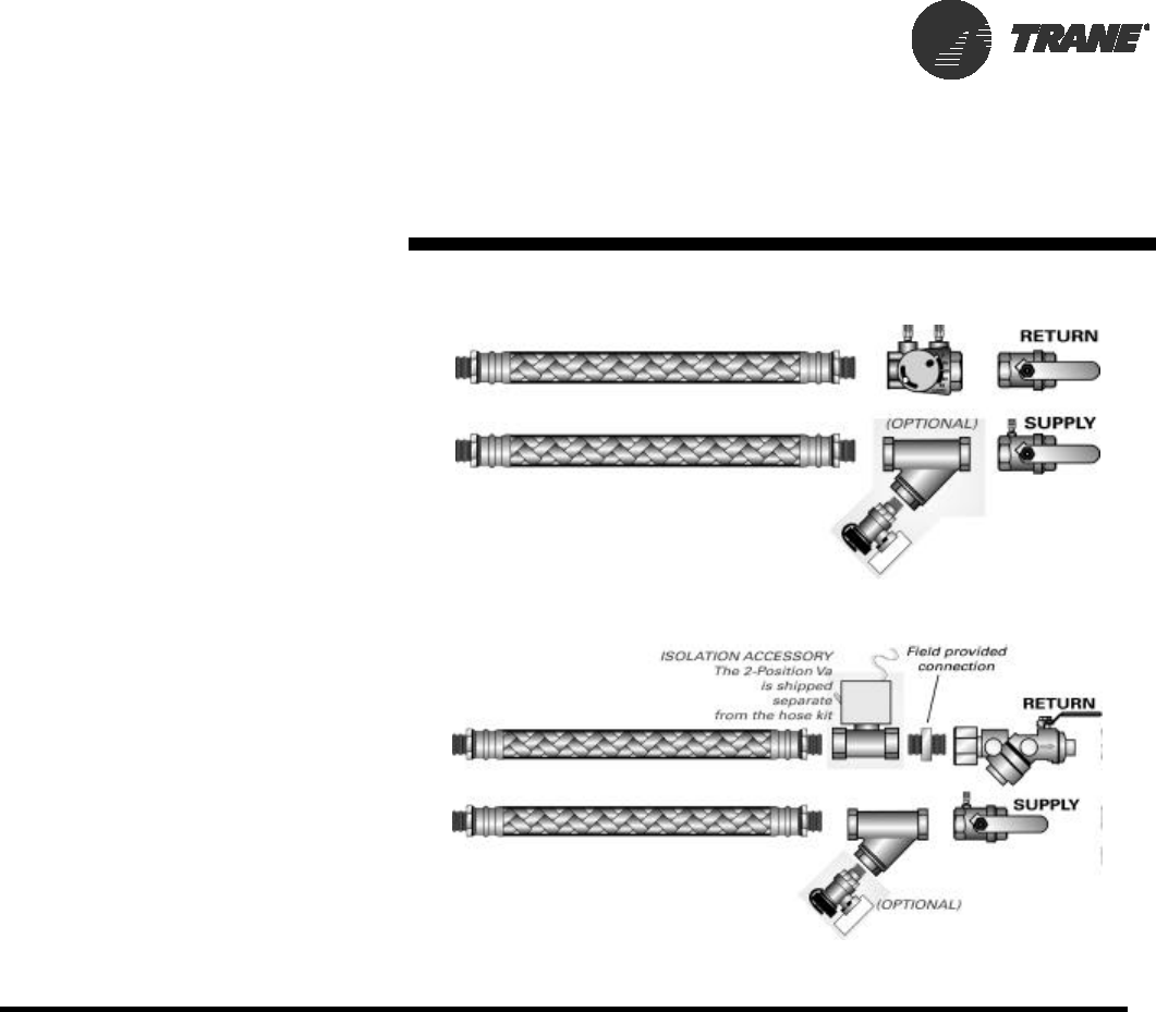
Types of Hose Connections
(3) A circuit setter provides a means of
manually balancing the water flow to
the heat pump. This manual in-line
balancing method is accurate up to
±20%. In order to determine flow rate,
the user must record both handle posi-
tion, and differential pressure drop.
Then, the user must consult a chart
containing both pieces of information
and make the necessary adjustments
to the circuit setter.
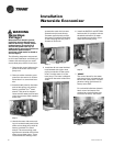
(4) For self balancing flow control, a
Hays Measurflo® balancing hose kit
provides a constant flow rate over the
pressure differential range of 2 to 80
psid. As system pressures change
(through the addition of heat pumps,
for example) each individual flow con-
trol valve will automatically adjust to
the new system conditions.
Additional accessories, such as a
strainer are recommended for use to
eliminate contaminants from entering
the co-axial water-to-refrigerant heat
exchanger.
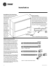
Cleaning and Flushing
the Water Loop
After the piping system is complete,
the flexible hose connectors should be
doubled back to complete the water
circuit external to the unit (avoiding
trash settle-out in the condenser). An
extra pipe may be necessary to con-
nect the hose kits.
(1) Water circulation system should be
filled with clean water using the water
make up connections. Note: Air vents
should be open during filling.
(2) With the air vents closed, start the
circulating pump and then crack the air
vents to bleed off the trapped air, as-
suring circulation through all compo-
nents of the system.
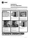
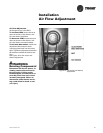
Installation
Option 3: Flexible hoses with ball valves and circuit setter
Option 4: Flexible hoses with automatic balancing flow control
Note: Make up water must be available
to the system to replace the volume
formerly occupied by the air that is
bled off.
(3) With the air vented and the water
circulating, the entire system should
be checked for leaks with repairs made
as required.
(4) Operate the supplementary heat
system (boiler) making checks per
manufacturer’s instructions. During
this operation, visual checks should be
made for leaks that may have occurred
due to increased heat. Repair as re-
quired.
(5) Open the system at the lowest point
for the initial blow down (making sure
the make up water is equal to the water
being dumped). Continue blow down
until the water leaving the drain runs
clear, but not less than 2 hours.
(6) Shut down pumps and supplemen-
tary heat system. Reconnect the hoses
placing the water-to-refrigerant heat
exchanger in the water circulating sys-
tem.
Note: Vents should be open when the
pumps and supplementary heat sys-
tem are shut down.