


WSHP-SVX01D-EN 5
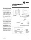
General
Information
Unit Nameplate
The unit nameplate is located on the
outside of the control box access panel
at the front of the unit. It includes the
unit model number, serial number,
electrical characteristics, refrigerant
charge, and other pertinent unit data.
Compressor Nameplate
The nameplate for the compressors
are located on the compressor shell.
Unit Description
Before shipment, each unit is leak test-
ed, dehydrated, charged with refriger-
ant and run tested for proper control
operation.
Air-to-Refrigerant Coil
The air-to-refrigerant coil is aluminum
fin, mechanically bonded to the cop-
per tubing.
Water-to-Refrigerant Coil
The water-to-refrigerant coil is a cop-
per or cupro-nickel (option) and steel
tube (tube-within-a-tube) design, leak
tested to assure there is no cross leak-
age between the water tube (copper/
cupro-nickel) and refrigerant gas (steel
tube).
Controls
The control system offered to con-
trol the unit is a Basic 24 Volt control
for the 1/2 through 5 ton sizes, a De-
luxe 24 Volt control option for all unit
sizes, a Tracer
TM
ZN510, LonTalk
TM
certified control option for the 1/2
through 5 ton unit sizes, or a Tracer
ZN524, LonTalk certified control op-
tion for all unit sizes.
All power wiring to the equipment is
made at the unit contactor for the 1/2
through 5 ton, and at the high voltage
terminal block for the 6 through 25 ton.
All low voltage wiring is made at the
unit’s low voltage terminal board.
System Input Devices and
Functions
A thermostat, zone sensor or building
automation system is required to op-
erate the water-source heat pump. The
flexibility of having several mode ca-
pabilities depends upon the type of
sensor and/or remote panel selected.
Troubleshooting and connection dia-
grams for the 24 Volt control systems
may be located in the back of this man-
ual. All digital control troubleshooting
tips and connection diagrams are lo-
cated in WSHP-IOP-2 (ZN510) or
WSHP-PRB002-EN (ZN524).
Basic 24V Controls
Safety devices for equipment contain-
ing the basic 24V control option in-
clude a low pressure switch or suction
line temperature sensor to prevent
compressor operation during low tem-
perature activity. The switch or sensor
is set to activate at refrigerant pres-
sures of 20 psig (1/2 to 5 ton units) or
7 psig (6 to 25 ton units) to fit most ap-
plications.
A high pressure switch prevents com-
pressor operation during high or ex-
cessive discharge pressures
exceeding 395 psig.
The lockout relay communicates the
low or high pressure situation to the
compressor to prevent operation. For
units that contain a condensate over-
flow switch option, a condensate over-
flow situation will also be
communicated to the compressor
through the lockout relay if an over-
flow condition exists. The relay may
be reset at the thermostat, or by cy-
cling power to the unit.
General alarm is accomplished
through the lockout relay and is used
in driving light emitting diodes (LEDs).
This feature will drive dry contacts
only, and cannot be used to drive field
installed control inputs.
(option) Deluxe 24V Controls
Units containing the Deluxe 24V con-
trol design will incorporate a micro-
processor-based control board. The
Trane microprocessor board is factory
wired to a terminal strip to provide all
necessary terminals for field connec-
tion. The deluxe board is equipped
with a random start relay, anti-short
cycle timer, brown out protection,
compressor disable, condensate over-
flow, unit safety control, diagnostics
and a generic relay (which may be
available for field use). See page 56 for
diagnostic information and thermostat
connections.
(option) Tracer ZN510 or ZN524
Controls
The digital ZN510 and ZN524 control-
ler is designed to support the 1/2
through 25 ton water-source heat
pumps in either a standalone, peer-to-
peer with a Tracer Loop Controller, or
as a full building automation (open
protocal) system. The 1/2 through 5
ton units that incorporate direct digital
controls will typically come equipped
with the ZN510 control board. The ex-
ception to this would be if the equip-
ment contained hot gas reheat,
waterside economizer, or boilerless
control with electric heat. The ZN524
digital control board is designed to in-
terface and run these mechanical op-
tions. All units over 5 tons would ship
with the Tracer ZN524 control board.
For installation, operation and diag-
nostics of the ZN510 and ZN524
WSHP-IOP-2 (ZN510) and/or WSHP-
PRB002-EN (ZN524).
(option) Waterside Economizer
Instructions for mechanical connec-
tion of the waterside economizer to
the water-source heat pump may be
found in the dimensional section of
this manual.
The waterside economizer is designed
to begin economizing mode when wa-
ter temperatures fall below the field
adjustable temperature of 25, 35, 45,
55 or 65 F (for the Deluxe control op-
tion), or below the programmed set-
point (for the ZN524 control option).
When the temperature is less than the
setpoint, fluid will flow into the econo-
mizing coil, while simultaneously halt-
ing mechanical operation of the
compressor. Mechanical cooling will
continue on a call for a second stage
from the thermostat or system control.