


48 WSHP-SVX01D-EN
General Installation Checks
The checklist below is a summary of
the steps required to successfully in-
stall a commercial unit. This checklist
is intended to acquaint the installing
personnel with what is required in the
installation process. It does not re-
place the detailed instructions called
out in the applicable sections of this
manual.
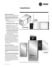
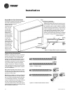
1 Remove packaging and inspect the
unit. Check the unit for shipping
damage and material shortage; file
a freight claim and notify appropri-
ate sales representation.
Note: The 1/2 through 5 ton units
have been tied to the skid by (2)
shipping bolts. The removal of
these bolts will require a 3/8" (9.7
mm) ratchet with a 1/2" (12.7 mm)
socket.
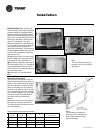
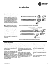
The GEV 6 through 25 ton units
have been anchored to the skid
with (4) angle brackets. Remove
these brackets before lifting unit
into place.
The GEH 6 through 15 ton units are
anchored to the cross brace of the
skid with (4) wood screws. Re-
move these screws prior to lifting
the unit into place.
2 Verify the correct model, options
and voltage from the unit name-
plate.
3 Pull out all field attached parts (i.e.
filter rack, duct collar, filter and
mounting screws) from the unit
packaging for field mounting.
4 Verify the installation location of
the unit will provide the required
clearance for proper operation.
5 Remove refrigeration access panel
and inspect the unit. Be certain the
refrigerant tubing has clearance
from adjacent parts.
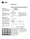
6 Fabricate and install duct work.
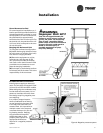
7 Install and connect a condensate
drain line and trap to the drain
connection.
WARNING
Hazardous
Voltage!
Disconnect all electric power,
including remote disconnects
before servicing. Follow proper
lockout/tagout procedures to
ensure the power can not be
inadvertently energized. Failure to
disconnect power before
servicing could result in death or
serious injury.
Main Electrical
8 Verify the power supply complies
with the unit nameplate specifica-
tions.
9 Inspect all control panel compo-
nents; tighten any loose connec-
tions.
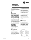
10 Connect properly sized and pro-
tected power supply wiring to a
field-supplied/installed discon-
nect switch and to the main pow-
er terminal block 1K1 for 1/2
through 5 ton equipment or
1TB1 for 6 through 25 ton equip-
ment in the unit control panel.
11 Install proper grounding wires to
an earth ground.
Note: All field-installed wiring must
comply with NEC and applicable local
codes.
Electric Heat Requirements
12 Verify that the power supply com-
plies with the electric heater
specifications on the unit and
heater nameplate.
13 Inspect the heater junction box
and control panel; tighten any
loose connections.
14 Check electric heat circuits for
continuity.
Low Voltage Wiring (AC & DC)
Requirements
15 Install the zone thermostat, with
or without switching subbase.
16 Connect properly sized control
wiring to the proper termination
points between the zone thermo-
stat and the unit control panel.
Filter Installation
17 Each unit ships with 1" (25.4) or 2"
(50.8 mm) filters. The quantity of
filters is determined by unit size.
The horizontal1/2 through 5 ton
units requires a field installation
of the 1"/2" filter rack. All sheet-
metal bracket, filter and hardware
are in a box located on the side of
the unit within the unit packaging.
All 1/2 through 25 ton verticals
and 6 through 15 ton horizontal
units ship with the filter rack and
filters factory installed.
Note: Do not operate the unit without
filters.
Installation