21RT-PRC010-EN
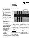
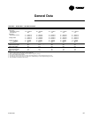
1. EXAMPLE: Model numbers: SFHFC55FHA55C69D3001N describes a unit with the following characteristics: DX
cooling with natural gas heating, 55 ton nominal cooling capacity, 230/60/3 power supply, high heat model. 100
percent exhaust with Statitrac, 7.5 HP exhaust fan motor with drive selection No. 5 (500 RPM), high-efficiency
throwaway filters, 20 HP supply fan motor with drive selection No. 9 (900 RPM), 0-100% economizer, VAV supply air
temperature control with inlet guide vanes, no remote panel, standard ambient control, U.L. agency approval. The
service digit for each model number contains 38 digits; all 38 digits must be referenced.
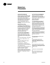
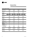
2. EXAMPLE: Model numbers: SXHGD1140AH7CF8D3001 describes a unit with the following characteristics: DX
cooling with extended casing, no heat, 105 ton nominal cooling capacity, 460/60/3 power supply, no heat, 100
percent exhaust with Statitrac, 30 h.p. exhaust fan motor with drive selection No. 7 — (700 RPM), high-efficiency
throwaway filters, 60 hp supply fan motor with drive selection No. 8 — (900 RPM), economizer, VAV supply air
temperature control with inlet guide vanes, no remote panel, standard ambient, UL agency approval. The service
digit for each model number contains 36 digits; all 36 digits must be referenced.
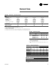
3. Available as standard 460 volt only for 70 and 75 ton models.
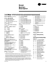
Model
Number
Description
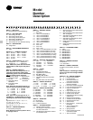
S X H G D 1 1 4 O A H 7 C F 9 D 3 0 0 1 0 0 0 0 0 0 0 0 0 0 0 0 0 0 0 0
2
1 2 3 4 567 8 9 10111213141516171819 2021222324252627 282930313233343536
DIGIT 1 — UNIT TYPE
S = Self-Contained (Packaged Rooftop)
DIGIT 2 — UNIT FUNCTION
E = DX Cooling, Electric Heat
F = DX Cooling, Natural Gas Heat
L = DX Cooling, Hot Water Heat
S = DX Cooling, Steam Heat
X = DX Cooling, No Heat, Extended Casing
DIGIT 3 — UNIT AIRFLOW
H = Single Zone
DIGIT 4 — DEVELOPMENT SEQUENCE
G = Seventh
DIGITS 5,6,7 — NOMINAL CAPACITY
C90 = 90 Tons
D11 = 105 Tons
D12 = 115 Tons
D13 = 130 Tons
DIGIT 8 — POWER SUPPLY
4 = 460/60/3 XL
5 = 575/60/3 XL
E = 200/60/3 XL
F = 230/60/3 XL
DIGIT 9 — HEATING CAPACITY
0 = No Heat
H = High Heat - 2-Stage
J = High Heat - Limited Modulation
P = High Heat - Full Modulation
Note:
When the second digit calls for “E”
(electric heat), the following values apply
in the ninth digit:
W = 190 KW
When the second digit calls for ‘’L’’ or
‘’S’’, one of the following valve size
values must be in Digit 9:
High Heat Coil: 3 = 1.0”, 4 = 1.25”, 5 =
1.50”, 6 = 2.0”, 7 = 2.5”
Low Heat Coil: C = 1.0”, D = 1.25”, E =
1.50”, F = 2.0”, G = 2.5”
DIGIT 10 — DESIGN SEQUENCE
A = First (Factory Assigned)
Note: Sequence may be any letter A thru
Z, or any digit 1 thru 9.
DIGIT 11 — EXHAUST OPTION
0 = None
7 = 100%, 15 HP W/Statitrac
4 = Space Pressure Control with Exhaust
VFD w/o Bypass
5 = Space Pressure Control with Exhaust
VFD and Bypass
6 = VAV Supply Air Temperature Control
with VFD w/o Bypass
7 = VAV Supply Air Temperature Control
with VFD and Bypass
8 = Supply and Exhaust Fan with VFD
w/o Bypass
9 = Supply and Exhaust Fan with VFD
and Bypass
DIGIT 18 — ACCESSORY PANEL
0 = None
A = BAYSENS008*
B = BAYSENS010*
C = BAYSENS013*
D = BAYSENS014*
E = BAYSENS019*
F = BAYSENS020*
G = BAYSENS021*
DIGIT 19 — AMBIENT CONTROL
0 = Standard
DIGIT 20 — AGENCY APPROVAL
0 = None (UL Gas Heater, see note)
1=UL
2 = CSA
Note: Includes UL classified gas heating
section only, when second digit of Model
No. is a “F.”
DIGITS 21 - 36 — MISCELLANEOUS
21 A = Unit Disconnect Switch
22 B = Hot Gas Bypass (CV Only)
23 D = Economizer Control w/
Comparative Enthalpy
23 R = Economizer Control w/
Reference Enthalpy
23 T = Economizer Control w/Dry Bulb
24 E = Low Leak Fresh Air Dampers
25 F = High Duct Temperature
Thermostat
26 G = High Capacity Evaporator
Coil (90-105 Only)
27 K = Generic B.A.S. Module
28 L = High-Efficiency Motors
(Supply and Exhaust)
29 M = Remote Human Interface
30 N = Ventilation Override Module
31 R = Extended Grease Lines
32 T = Access Doors
33 V = Inter-Processor
Communication Bridge
34 Y = Trane Communication
Interface Module
35 5 = VFD Line Reactor
36 6 = Factory-Powered 15A GFI
Convenience Outlet
8 = 100%, 20 HP W/Statitrac
9 = 100%, 25 HP W/Statitrac
F = 50%, 15 HP
H = 100%, 30 HP W/Statitrac
J = 100%, 40 HP W/Statitrac
K = 100%, 15 HP W/O Statitrac (CV Only)
L = 100%, 20 HP W/O Statitrac (CV Only)
M = 100%, 25 HP W/O Statitrac (CV Only)
N = 100%, 30 HP W/O Statitrac (CV Only)
P = 100%, 40 HP W/O Statitrac (CV Only)
DIGIT 12 — EXHAUST AIR FAN DRIVE
0 = None
5 = 500 RPM
6 = 600 RPM
7 = 700 RPM
8 = 800 RPM
DIGIT 13 — FILTER
A = Throwaway
C = High-Efficiency Throwaway
D = Bag With Prefilter
E = Cartridge With Prefilter
F = Throwaway Filter Rack Less Filter
Media
G = Bag Filter Rack Less Filter Media
DIGIT 14 — SUPPLY AIR FAN HP
C = 30 HP (2-15 HP)
D = 40 HP (2-20 HP)
E = 50 HP (2-25 HP)
F = 60 HP (2-30 HP)
G = 80 HP (2-40 HP)
DIGIT 15 — SUPPLY AIR FAN DRIVE
9 = 900 RPM
A = 1000 RPM
B= 1100 RPM
C= 1200 RPM
D= 1300 RPM
E= 1400 RPM
F = 1500 RPM
G= 1600 RPM
DIGIT 16 — FRESH AIR
D = 0-100% Economizer (Std.)
DIGIT 17 — SYSTEM CONTROL
1 = Constant Volume Control
2 = VAV Supply Air Temperature Control
w/o Inlet Guide Vanes
3 = VAV Supply Air Temperature Control
w/ Inlet Guide Vanes


