RT-PRC010-EN14
exchanger, leading to premature failure.
For increased reliability, the
recommendation in these applications is
full modulation gas heat. For airflow
limitations and temperature rise across
the heat exchanger information, see
Table PD-24, 25 and RT-EB-104.
Acoustical Considerations
The ideal time to make provisions to
reduce sound transmission to the space
is during the project design phase.
Proper placement of rooftop equipment
is critical to reducing transmitted sound
levels to the building. The most
economical means of avoiding an
acoustical problem is to place any
rooftop equipment away from
acoustically critical area. If possible,
rooftop equipment should not be located
directly above areas such as: offices,
conference rooms, executive office areas
and classrooms. Ideal locations are
above corridors, utility rooms, toilet
facilities, or other areas where higher
sound levels are acceptable.
Several basic guidelines for unit
placement should be followed to
minimize sound transmission through
the building structure:
1
Never cantilever the condensing section
of the unit. A structural cross member
must support this end of the unit.
2
Locate the unit’s center of gravity close
to or over a column or main support
beam to minimize roof deflection and
vibratory noise.
3
If the roof structure is very light, roof
joists should be replaced by a structural
shape in the critical areas described
above.
4
If several units are to be placed on one
span, they should be staggered to
reduce deflection over that span.
It is impossible to totally quantify the
effect of building structure on sound
transmission, since this depends on the
response of the roof and building
members to the sound and vibration of
the unit components. However, the
guidelines listed above are experience
proven guidelines which will help reduce
sound transmission.
There are several other sources of unit
sound, i.e., supply fan, compressors,
exhaust fans, condenser fans and
aerodynamic noise generated at the duct
fittings. Refer to the ASHRAE
Applications Handbook, Chapter 42, 1991
edition for guidelines for minimizing the
generation of aerodynamic noise
associated with duct fittings.
Trane’s Engineering Bulletin RT-EB-80
describes various duct installation
considerations specifically addressing
indoor sound level concerns. This
bulletin includes sound power data on
Trane’s IntelliPak Rooftops 20 to 130 tons.
Ask your local Trane representative for
this informative engineering bulletin.
The VariTrane® Computerized Duct
Design Program can be used to analyze
the truck duct, run-out duct, VAV control
unit and terminal unit noise attenuation.
This program quantifies the airborne
sound generation that can be expected
in each terminal so that the designer can
identify potential sound problems and
make design alterations before
equipment installation.
The Trane Acoustics Program (TAP)
allows modeling of rooftop installation
parameters. The output of this program
shows the resulting indoor NC level for
the modeled installation. This program is
available from Trane’s Customer Direct
Service Network™ (C.D.S.), ask your
local Trane representative for additional
information on this program.
Clearance Requirements
The recommended clearances identified
with unit dimensions should be
maintained to assure adequate
serviceability, maximum capacity and
peak operating efficiency. A reduction in
unit clearance could result in condenser
coil starvation or warm condenser air
recirculation. If the clearances shown are
not possible on a particular job, consider
the following:
• Do the clearances available allow for
major service work such as changing
compressors or coils?
• Do the clearances available allow for
proper outside air intake, exhaust air
removal and condenser airflow?
• If screening around the unit is being
used, is there a possibility of air
recirculation from the exhaust to the
outside air intake or from condenser
exhaust to condenser intake?
Actual clearances which appear
inadequate should be reviewed with a
local Trane sales engineer.
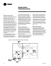
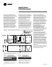
When two or more units are to be placed
side by side, the distance between the
units should be increased to 150 percent
of the recommended single unit
clearance. The units should also be
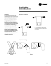
staggered as shown in Figure AC-4 for
two reasons:
1
To reduce span deflection if more than
one unit is placed on a single span.
Reducing deflection discourages sound
transmission.
2
To assure proper diffusion of exhaust air
before contact with the outside air intake
of adjacent unit.
Application
Considerations


