RT-PRC010-EN20
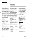
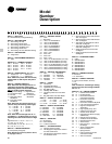
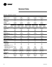
Model
Number
Description
DIGIT 1 — UNIT TYPE
S = Self-Contained (Packaged Rooftop)
DIGIT 2 — UNIT FUNCTION
A = DX Cooling, No Heat
E = DX Cooling, Electric Heat
F = DX Cooling, Natural Gas Heat
L = DX Cooling, Hot Water Heat
S = DX Cooling, Steam Heat
X = DX Cooling, No Heat, Extended Casing
DIGIT 3 — UNIT AIRFLOW
H = Single Zone
DIGIT 4 — DEVELOPMENT SEQUENCE
F = Sixth
DIGITS 5,6,7 — NOMINAL CAPACITY
C20 = 20 Tons C55 = 55 Tons
C25 = 25 Tons C60 = 60 Tons
C30 = 30 Tons C70 = 70 Tons
C40 = 40 Tons C75 = 75 Tons
C50 = 50 Tons
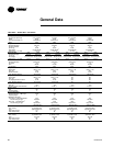
DIGIT 8 — POWER SUPPLY (See Notes)
4 = 460/60/3 XL E = 200/60/3 XL
5 = 575/60/3 XL F = 230/60/3 XL
Note: SEHF units (units with electric heat)
utilizing 208V or 230V require dual power
source.
DIGIT 9 — HEATING CAPACITY
Note: When the second digit calls for “F”
(Gas Heat), the following values apply:
Additionally, please note G and M available
ONLY on 50 Ton models and above.
H = High Heat-2-Stage P = High Heat-Full
L = Low Heat-2-Stage Modulation
0 = No Heat M = Low Heat-Full
J = High Heat-Limited Modulation
Modulation
G = Low Heat-Limited
Modulation
Note: When the second digit calls for “E”
(electric heat), the following values apply:
D = 30 KW R = 130 KW
H = 50 KW U = 150 KW
L = 70 KW V = 170 KW
N = 90 KW W = 190 KW
Q = 110 KW
Note: When the second digit calls for ‘’L’’
(Hot Water) or ‘’S’’(Steam) Heat, one of the
following valve size values must be in Digit
9:
High Heat Coil: 1 = .50”, 2 = .75”, 3 = 1”,
4 = 1.25”, 5 = 1.5”, 6 = 2”.
Low Heat Coil: A = .50”, B = .75”, C = 1”,
D = 1.25”, E = 1.5”, F = 2”.
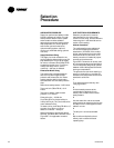
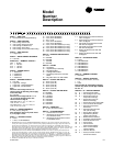
DIGIT 10 — DESIGN SEQUENCE
A = First (Factory Assigned)
DIGIT 11 — EXHAUST OPTION
0 = None
1 = Barometric
2 = 100%, 1.5 HP W/Statitrac
3 = 100%, 3 HP W/Statitrac
4 = 100%, 5 HP W/Statitrac
5 = 100%, 7.5 HP W/Statitrac
6 = 100%, 10 HP W/Statitrac
7 = 100%, 15 HP W/Statitrac
8 = 100%, 20 HP W/Statitrac
A = 50%, 1.5 HP
B = 50%, 3 HP
C = 50%, 5 HP
D = 50%, 7.5 HP
E = 100%, 1.5 HP W/O Statitrac (CV Only)
F = 100%, 3 HP W/O Statitrac (CV Only)
G = 100%, 5 HP W/O Statitrac (CV Only)
H = 100%, 7.5 HP W/O Statitrac (CV Only)
J = 100%, 10 HP W/O Statitrac (CV Only)
K = 100%, 15 HP W/O Statitrac (CV Only)
L = 100%, 20 HP W/O Statitrac (CV Only)
DIGIT 12 — EXHAUST AIR FAN DRIVE
0 = None 8 = 800 RPM
4 = 400 RPM 9 = 900 RPM
5 = 500 RPM A = 1000 RPM
6 = 600 RPM B = 1100 RPM
7 = 700 RPM
DIGIT 13 — FILTER
A = Throwaway
B = Cleanable Wire Mesh
C = High-Efficiency Throwaway
D = Bag With Prefilter
E = Cartridge With Prefilter
F = Throwaway Filter Rack Less Filter
Media
G = Bag Filter Rack Less Filter Media
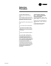
DIGIT 14 — SUPPLY AIR FAN HP
1 = 3 HP 4 = 10 HP 7 = 25 HP
2 = 5 HP 5 = 15 HP 8 = 30 HP
3 = 7.5 HP 6 = 20 HP 9 = 40 HP
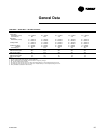
3
DIGIT 15 — SUPPLY AIR FAN DRIVE
5 = 500 RPM B = 1100 RPM
6 = 600 RPM C = 1200 RPM
7 = 700 RPM D = 1300 RPM
8 = 800 RPM E = 1400 RPM
9 = 900 RPM F = 1500 RPM
A= 1000 RPM G = 1600 RPM
DIGIT 16 — FRESH AIR
A = No Fresh Air
B = 0-25% Manual
D = 0-100% Economizer
DIGIT 17 — SYSTEM CONTROL
1 = Constant Volume Control
2 = VAV Supply Air Temperature Control
w/o Inlet Guide Vanes
3 = VAV Supply Air Temperature Control
w/ Inlet Guide Vanes
4 = Space Pressure Control with Exhaust
VFD w/o Bypass
5 = Space Pressure Control with Exhaust
VFD and Bypass
6 = VAV Supply Air Temperature Control
with VFD w/o Bypass
7 = VAV Supply Air Temperature Control
with VFD and Bypass
8 = Supply and Exhaust Fan with VFD
w/o Bypass
9 = Supply and Exhaust Fan with VFD
and Bypass
DIGIT 18 — ACCESSORY PANEL
0 = None
A = BAYSENS008*
B = BAYSENS010*
C = BAYSENS013*
D = BAYSENS014*
E = BAYSENS019*
F = BAYSENS020*
G = BAYSENS021*
DIGIT 19 — AMBIENT CONTROL
0 = Standard
1 = 0° Fahrenheit
DIGIT 20 — AGENCY APPROVAL
0 = None (UL Gas Heater, see note)
1 = UL
2 = CSA
Note: Includes UL classified gas heating
section only when second digit of Model
No. is a “F.”
DIGITS 21 - 38 — MISCELLANEOUS
21 A = Unit Disconnect Switch
22 B = Hot Gas Bypass
23 D = Economizer Control w/
Comparative Enthalpy
23 R = Economizer Control w/
Reference Enthalpy
23 T = Economizer Control w/Dry Bulb
24 E = Low Leak Fresh Air Dampers
25 F = High Duct Temperature
Thermostat
26 G = High Capacity Evap. Coil
27 H = Copper Fins (Cond. Only)
28 K = Generic B.A.S. Module
29 L = High-Efficiency Motors (Supply
and Exhaust)
30 M = Remote Human Interface
31 N = Ventilation Override Module
32 R = Extended Grease Lines
33 T = Access Doors
34 V = Inter-Processor Communica
tion Bridge
35 Y = Trane Communication
Interface Module
36 8 = Spring Isolators
37 6 = Factory-Powered 15A GFI
Convenience Outlet
38 5 = VFD Line Reactor
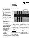
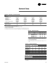
S F H F C 5 5 F H A 5 5 C 6 9 D 3 0 0 1 0 0 0 0 0 0 0 0 0 0 0 0 0 0 0 0 0 0
1
1 2 3 4 5 6 7 8 9 101112131415161718192021222324252627 28 29 30 31 32 33 34 35 36 37 38
Note: Sequence may be any letter A thru Z,
or any digit 1 thru 9.


