103RT-PRC010-EN
Mechanical
Specifications
Heating System
Electric heating option
All electric heat models shall be
completely assembled and have wired
electric heating system integral within
the rooftop unit. Heavy duty nickel
chromium elements internally wired
with a maximum density of 40 watts per
square inch shall be provided. Heater
circuits shall be 48 amps or less, each
individually fused. Automatic reset high
limit control shall operate through heater
backup contactors. The 460 and 575 volt
electric units shall have optional factory
mounted non-fused disconnect switch
located in the main control panel to
serve the entire unit. The 200 and 230
volt SEHF models shall have separate
power supply to heating section. All
voltages of the SEHG models shall have
single power supply to serve the entire
unit.
Steam heating option
Steam coils shall be Type NS, with non-
freeze steam distribution circuits.
Distributor tubes shall be located
concentrically within condensing tubes
to assure even steam distribution. Coils
shall be pitched to provide complete
drainage. Steam modulating valve with
actuator shall be provided.
Hot water heating option
Hot water coils shall be Type W and
factory mounted in the rooftop unit to
provide complete drainage of coil. Hot
water modulating valve with actuator
shall be provided.
Gas-fired heating option
All gas-fired units shall be completely
assembled and have a wired gas fired
heating system integral within unit. Units
shall be UL or CSA approved specifically
for outdoor applications downstream
from refrigerant cooling coils. All gas
piping shall be threaded connection with
a pipe cap provided. Gas supply
connection shall be provided through
the side or bottom of unit. All units shall
be fire tested prior to shipment.
• Heat Exchanger shall be tubular two
pass design with 16-gauge stainless
steel primary and 18-gauge stainless
steel secondary heat exchanger
surfaces. Free floating design shall
eliminate expansion and contraction
stresses and noises. Gasketed cleanout
plate shall be provided for cleaning of
tubes/turbulators. Heat exchanger shall
be factory pressure and leak tested.
• Burner shall be industrial type burner
with a air proving switch to prevent
burner operation if burner is open for
maintenance or inspection. Ceramic
cone shall be provided to shape the
flame to prevent impingement on
sides of heat exchanger drum. Burner
assembly shall house ignition and
monitoring electrode.
• Combustion Blower shall be
centrifugal type fan to provide air
required for combustion. Fan motor
shall have built-in thermal overload
protection.
• Gas Safety Controls shall include
electronic flame safety controls to
require proving of combustion air prior
to ignition sequence which shall
include a 60 second pre-purge cycle.
Direct spark ignition shall be provided
on 235 and 350 MBh heat exchangers
and pilot ignition shall be provided on
500, 850 and 1000 MBh heat
exchanger units. Sixty second delay
shall be provided between first and
second stage gas valve operation on
two-stage heaters. Continuous
electronic flame supervision shall be
provided as standard.
• Full Modulation Gas Heaters shall be
made from grades of stainless steel
suitable for condensing situations. The
heater shall have a turn down ratio of
at least 4 to 1.
• Limited Modulation Gas Heaters shall
have a minimum turn down ratio of at
least 3 to 1.
Accessories
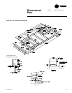
Roof Mounting Curb
Roof mounting curb shall be fourteen
gauge zinc coated steel with nominal
two-inch by four-inch nailer setup.
Supply/return air opening gasketing
shall be provided. Curb shall ship
knocked down for easy assembly.
Channel shall be provided to allow for
adjustment of return air opening
location. Curb shall be manufactured to
National Roofing Contractors
Association guidelines.
Electronic Zone Sensors
• Zone Sensors shall provide two
temperature setpoint levers, Heat,
Auto, Off, or Cool system switch, Fan
Auto or Fan On switch. Optional status
indication LED lights, System On,
Heat, Cool, and Service shall be
available. These sensors shall be
used with CV units.
• Programmable Night Setback Sensors
shall be electronic programmable
sensors with auto or manual
changeover with 7 day programming.
Keyboard shall provide selection of
Heat, Cool, Fan Auto or On. All
programmable sensors shall have
System On, Heat, Cool, Service LED/
indicators as standard. Night setback
sensors shall have (1) Occupied,
(1) Unoccupied and (2) Override
programs per day. Sensors shall be
available for CV zone temperature
control and VAV Supply Air
temperature control.
• VAV zone sensor shall be provided
with supply air single temperature
setpoint and AUTO/OFF system switch.
Status indication LED lights shall
include: System On, Heat, Cool and
Service. Sensor shall be provided for
zone temperature control with VAV
units.
• Remote Sensor shall be available to be
used for remote zone temperature
sensing capabilities when zone
sensors are used as Remote panels.
• Fast Warm-Up Sensor shall be used
as Morning warm-up sensor with
VAV units.
• Integrated Comfort™ System sensors
shall be available with sensor only,
sensor with timed override, and sensor
with local temperature setpoint
adjustment with timed override.
• Remote Minimum Position
Potentiometer shall be available to
remotely adjust the minimum position
setting of the unit’s economizer.


