


Performance Tests
TDS 520A, 524A, 540A, & 544A Performance Verification
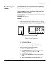
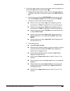
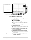
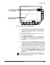
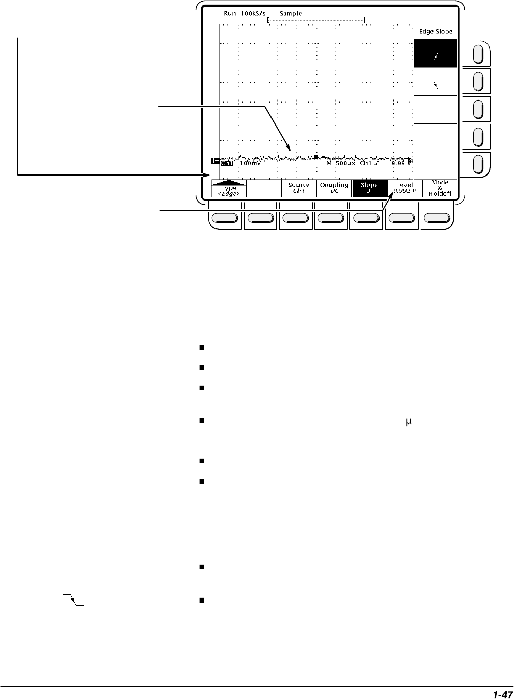
First, set vertical offset to maximum
and vertical position to –3 divisions.
Second, set input equal to
the offset to return the DC
level to the screen.
Third, push SET LEVEL to
50% and check the results in
the main menu under “Level.”
Figure 1-17: Measurement of Trigger-level Accuracy
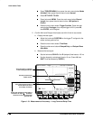
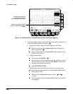
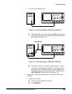
3.
Confirm Delayed trigger system is within limits for Trigger-level/Threshold
accuracy:
a.
Select the Delayed time base:
Press HORIZONTAL MENU.
Press the main-menu button Time Base.
Press the side-menu buttons Delayed Only and Delayed Trig-
gerable.
Set D (delayed) horizontal SCALE to 500 s.
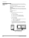
b.
Select the Delayed trigger system:
Press SHIFT; then press the front-panel button DELAYED TRIG.
Press the main-menu button Level.
c.
Measure the test signal:
Press the
side-menu button
SET TO 50%.
The TRIG’D indicator should be lit. Read the measurement results in
the side menu below the label Level.
d.
Check against limits:
Do the following subparts in the order listed.
CHECK that the Level readout in the side menu is within 9.940 V
to 10.060 V, inclusive.
Press the main-menu button Slope; then press the side-menu
button for negative slope. (See icon at left.) Press the main-menu
button Level. Repeat substep c.