Performance Tests
Performance Verification Procedures
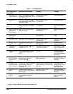
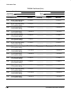
Table 1-1: Test Equipment
Item Number and
Description
Minimum Requirements Example Purpose
1 Attenuator,10X
(three required)
Ratio: 10X; impedance 50 ;
connectors: female BNC input,
male BNC output
Tektronix part number
011–0059–02
Signal Attenuation
2 Attenuator, 5X Ratio: 5X; impedance 50 ;
connectors: female BNC input,
male BNC output
Tektronix part number
011–0060–02
Signal Attenuation
3 Terminator, 50 Impedance 50 ; connectors:
female BNC input, male BNC
output
Tektronix part number
011–0049–01
Signal Termination
for Channel Delay
Test
4 Cable, Precision
50 Coaxial
(two required)
50 , 36 inch, male to male
BNC connectors
Tektronix part number
012–0482–00
Signal Interconnec-
tion
5 Connector, Dual-
Banana (two
required)
Female BNC to dual banana Tektronix part number
103–0090–00
Various Accuracy
Tests
6 Connector, BNC
“T”
Male BNC to dual female BNC Tektronix part number
103–0030–00
Checking Trigger
Sensitivity
7 Coupler, Dual-
Input
Female BNC to dual male
BNC
Tektronix part number
067–0525–02
Checking Delay
Between Channels
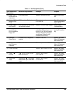
8 Generator, DC
Calibration
Variable amplitude to 10 V;
accuracy to 0.1%
Data Precision 8200, with
1 kV option installed
Checking DC Offset,
Gain, and Measure-
ment Accuracy
9 Generator, Cali-
bration
500 mV square wave calibra-
tor amplitude; accuracy to
0.25%
PG 506A
1
To check accuracy
of the CH 3 Signal
Out (TDS 540A and
544A only)
10 Generator, Lev-
eled Sine Wave,
Medium-Fre-
quency
200 kHz to 250 MHz; Variable
amplitude from 5 mV to
5.5 V
p-p
into 50
Tektronix SG 503 Leveled Sine
Wave Generator
1
Checking Trigger
Sensitivity at low fre-
quencies
11 Generator, Lev-
eled Sine Wave,
High-Frequency
250 MHz to 500 MHz; Variable
amplitude from 500 mV to
4
V
p-p
into 50 ; 6 MHz
reference
Tektronix SG 504 Leveled Sine
Wave Generator
1
with its Level-
ing Head
Checking Analog
Bandwidth and Trig-
ger Sensitivity at
high frequencies
12 Generator, Time
Mark
Variable marker frequency
from 10 ms to 10 ns; accuracy
within 2 ppm
Tektronix TG 501 Time
Mark Generator
1
Checking Sample-
Rate and Delay-time
Accuracy
13 Generator, Cali-
bration
500 mV square wave calibra-
tor amplitude; accuracy to
0.25%
PG 506A
1
Use to check accu-
racy of the CH 3
Output
1 Requires a TM 500 or TM 5000 Series Power Module Mainframe.


