


Performance Tests
TDS 520A, 524A, 540A, & 544A Performance Verification
2.
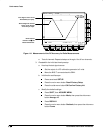
Confirm the input channels are within limits for analog bandwidth:
Do the
following substeps
—
test CH 1 first,
skipping substeps
a and b since
CH 1 is already set up for testing from step 1.
a.
Select an unchecked channel:
Press WAVEFORM OFF to remove the channel just confirmed
from display.
Press the front-panel button that corresponds to the channel you
are to confirm.
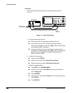
Move the leveling head to the channel you select.
b.
Match the trigger source to the channel selected:
Press TRIGGER MENU.
Press the main-menu button Source.
Press the side-menu button that corresponds to the channel
selected.
c.
Set its input impedance:
Press VERTICAL MENU; then press the main-menu button
Coupling.
Press the side-menu button to toggle it to the 50 setting.
d.
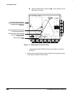
Set the vertical scale:
Set the vertical SCALE to one of the settings
listed in Table 1-5 not yet checked. (Start with the 100 mV setting.)
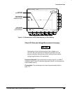
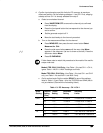
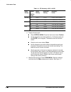
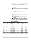
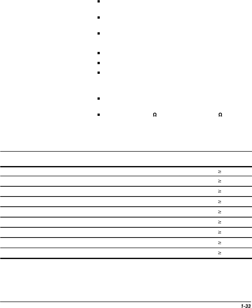
Table 1-5: Analog Bandwidth
Vertical
Scale
Attenuators
(10X)
Reference Amplitude
(at 6 MHz)
Horizontal
Scale
Test
Frequency
Limits
100 mV none 600 mV (6 divisions) 1 ns 500 MHz 424 mV
1 V none 5 V (5 divisions) 1 ns 500 MHz 3.535 V
500 mV none 3 V (6 divisions) 1 ns 500 MHz 2.121 V
200 mV none 1.2 V (6 divisions) 1 ns 500 MHz 848 mV
50 mV 1 300 mV (6 divisions) 1 ns 500 MHz 212 mV
20 mV 1 120 mV (6 divisions) 1 ns 500 MHz 84 mV
10 mV 1 60 mV (6 divisions) 1 ns 500 MHz 42 mV
5mV 2 30 mV (6 divisions) 1 ns 500 MHz 21 mV
2mV 2 12 mV (6 divisions) 2 ns 350 MHz 8.48 mV