


Warranted Characteristics
Specifications
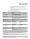
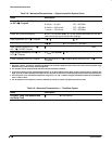
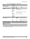
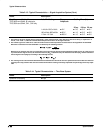
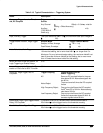
Table 2-8: Warranted Characteristics — Signal Acquisition System (Cont.)
Name Description
Analog Bandwidth, DC-50 Coupled
or DC-1 M Coupled
Volts/Div
5 mV/div – 10 V/div
2 mV/div – 4.98 mV/div
1 mV/div – 1.99 mV/div
Bandwidth
4
DC – 500 MHz
DC – 350 MHz
DC – 250 MHz
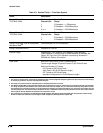
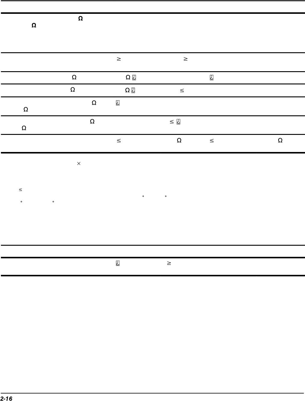
Cross Talk (Channel Isolation) 100:1 at 100 MHz and 30:1 at the derated bandwidth for any two
channels having equal volts/division settings
Input Impedance, DC-1 M Coupled 1 M pF
Input Impedance, DC-50 Coupled
50 1.3:1 from DC – 500 MHz
Input Voltage, Maximum, DC-1 M ,
AC-1 M , or GND Coupled
MHz
Input Voltage, Maximum, DC-50 or
AC-50 Coupled
5 V
RMS
, with peaks V
Lower Frequency Limit, AC Coupled 10 Hz when AC–1 M Coupled; 200 kHz when AC – 50
Coupled
5
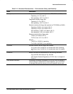
1 Net Offset = Offset – (Position Volts/Div). Net Offset is the nominal voltage level at the center of the A-D converter dynamic range.
Offset Accuracy is the accuracy of this Voltage level.
2 The samples must be acquired under the same setup and ambient conditions.
3 To ensure the most accurate measurements possible, run an SPC calibration first. When using the oscilloscope at a Volts/Div set-
ting 5 mV/div, an SPC calibration should be run once per week to ensure that instrument performance levels meet specifications.
4 The limits given are for the ambient temperature range of 0 C to +30 C. Reduce the upper bandwidth frequencies by 2.5 MHz for
each C above +30 C.
5 The AC Coupled Lower Frequency Limits are reduced by a factor of 10 when 10X, passive probes are used.
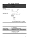
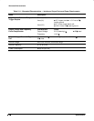
Table 2-9: Warranted Characteristics — Time Base System
Name
Description
Accuracy, Long Term Sample Rate
and Delay Time
1 ms interval