


Typical Characteristics
Specifications
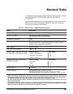
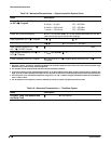
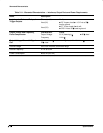
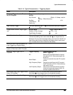
Table 2-13: Typical Characteristics — Signal Acquisition System (Cont.)
Name Description
Step Response Settling Errors
TDS 540A and 544A, all channels,
TDS 520A and 524A, CH1, CH2 only
Volts/Div Setting Step
Amplitude
Settling Error (%)
3
1 mV/div–99.5 mV/div
100 mV/div–995 mV/div
1 V/div–10 V/div
2 V
20 V
200 V
20 ns
0.5
1.0
1.0
100 ns
0.2
0.5
0.5
20 ms
0.1
0.2
0.2
1 The limits are given for signals having pulse height ≥ 5 div, reference level = 50% mid-point, filter set to Sin (x) /x acquired at ≥ 5
mV/div, 1.4
Tr
/
Si
5, where S
i
is the hardware sample interval and t
r
is the signal rise time.
2 The numbers given are valid 0 C to +30 C and will increase as the temperature increases due to the degradation in bandwidth.
Rise time is calculated from the bandwidth. It is defined by the following formula:
Note that if you measure rise time, you must take into account the rise time of the test equipment (signal source, etc.) that you use
to provide the test signal. That is, the measured rise time (RT
m
) is determined by the instrument rise time (RT
i
) and the rise time of
the test signal source (RTgen) according to the following formula:
3 The values given are the maximum absolute difference between the value at the end of a specified time interval after the mid-level
crossing of the step, and the value one second after the mid-level crossing of the step, expressed as a percentage of the step ampli-
tude.
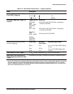
Table 2-14: Typical Characteristics — Time Base System
Name
Description
Aperture Uncertainty 5 ps