


Performance Tests
TDS 520A, 524A, 540A, & 544A Performance Verification
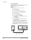
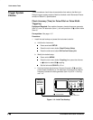
Connect the coupler to both CH 1 and CH 2.
2.
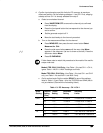
Confirm CH 1 through CH 4 (CH 2 for 520A and 524A) are within limits
for channel delay:
a.
Set up the generator:
Set the generator frequency to 250 MHz and
the amplitude for about five divisions in CH 1.
Hint: as you are adjusting the generator amplitude, push SET LEVEL
TO 50% frequently to speed up the updating of the waveform ampli-
tude on screen.
TDS 520A and 524A only: Press CH 2; then skip to substep e and
continue this check. If testing a TDS 540A or 544A model, continue
with the next substep, b.
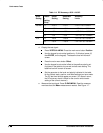
b.
Save a CH 2 waveform:
Press CH 2; then press save/recall WAVE-
FORM. Now, press the main-menu button Save Wfm
Ch2
; then
press the side-menu button To Ref 2.
c.
Save CH 3 waveform:
Move the coupler from CH 2 to CH 3, so that
CH 1 and CH 3 are driven. Press CH 3; then press the side-menu
button To Ref 3.
d.
Display all test signals:
Press WAVEFORM OFF twice to remove CH 2 and CH 3 from
the display.
Move the coupler from CH 3 to CH 4, so that CH 1 and CH 4 are
driven. Press CH 4.
Now, press the front-panel button MORE. Press the main-menu
buttons Ref 2 and Ref 3.
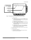
e.
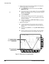
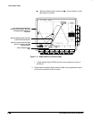
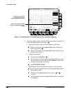
Measure the test signal:
Locate the point on the rising edge of the left-most waveform
where it crosses the center horizontal graticule line. This is the
time reference point
for this waveform. Note the corresponding
time reference point
for right-most waveform. See Figure 1-11.
Press CURSOR; then press the side-menu button V Bars.
Press CLEAR MENU.
Rotate the General Purpose knob to align one cursor to the
time
reference point
of the left-most waveform edge and the other
cursor to the
time reference point
of the right-most waveform
edge. (Press SELECT to switch between the two cursors.) See
Figure 1-11.