Appendix C: Chromaticity Reference
J17 Instruction Manual
C-5
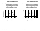
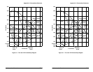
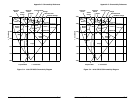
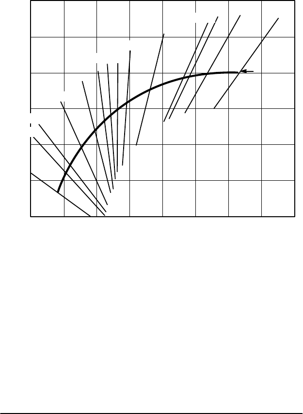
FigureĂCĆ3 shows selected isotemperature lines in the
x,y coordinate system. A light source along one of the
isotemperature lines will most nearly match the color
temperature of a blackbody radiator indicated for that
line.
0.200
0.250
0.300
0.350
0.400
0.450
0.500
0.200 0.250 0.300 0.350 0.400 0.450 0.500 0.550 0.600
20000
15000
10000
7500
6500
6000
5500
5000
4000
3000
2854
2500
2000
Planckian
Locus
x Coordinate
y Coordinate
8
Figure CĆ3:ăCorrelated Color Temperature Diagram
Although the colors displayed along an isotemperature
line will appear similar, there will be noticable differĆ
ences. For the best results when setting display color
balance, use the precise color coordinates of the
crossing of the Planckian Locus by the desired color
temperature. For example, x = 0.318 and Y = 0.332 is
the location of D65 (6500 K). Do not use correlated
color temperature alone.


