


Jaguar Model J-390
8
In this case, the maximum straight pipe vent length that can
be utilized with the 4 elbows would be: 100’ - (4’ x 10’) = 60’.
Since the air intake pipe also is PVC and requires the use of
4
elbows, the maximum straight pipe air intake length that
can be utilized is also 60 feet.
If the air for combustion were taken from the boiler room
(non-direct vent installation), still the maximum straight vent
length would be 60 feet.
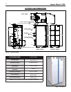
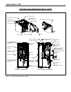
6. The Jaguar J-390 boiler is equipped with a built-in
c
ondensation drain and trap system. The traps must be
filled with water. DO NOT operate the boiler without filling
the trap with water to prevent flue gas discharge into space.
The drain must dispose of possibly large quantities of
condensate, which may require a neutralizing system. Refer
to the “Condensate Drainage” section of this manual. No
additional condensation drain and trap is required on the
vent piping system itself.
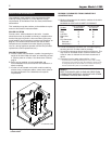
7. The horizontal vent pipe must be sloped upward from the
boiler at a pitch of at least 1/4” per 1 foot of run, so that
the condensate from the vent system runs to the boiler
vent adapter pipe, then out the built-in condensation drain
and trap.
8.
The horizontal vent and air intake pipes must be supported
with pipe straps, at intervals no greater than 5 feet, when
PVC/CPVC pipe is utilized. This support spacing applies
also to stainless steel vent pipe, unless the manufacturer’s
instructions permit otherwise. The vertical vent and air
intake pipes also must be supported, wherever the building
construction provides allowance for it, such as ceiling or
roof passage openings where a firestop and support or
braces can be affixed.
9. Minimum clearances of vent pipes from combustible
constructions must be maintained (see Page 4). No
clearance is required between the vent and air intake pipes
of this boiler.
10. Common venting with other appliances or another Jaguar
boiler is not allowed.
11. DO NOT install a vent damper or similar devices in vent
system or on the boiler.
12. DO NOT insulate venting system.
VENTING
INSTALLATION
Only PVC/CPVC and approved stainless steel materials listed
on page 6 may be used for the venting system installation. If
stainless steel vent systems are used, f
ollo
w the man
uf
actur-
er’
s instructions
, in conjunction with these instructions.
I. Non-Direct Vent Installation
The air for comb
ustion is tak
en from the ambient air
surrounding the boiler
;
theref
ore, ample supply of air is required
for combustion and ventilation (see page 6.)
DO
NOT use this installation method if the surrounding of the
boiler is contaminated. See page 5 for the list of harmful
contaminants and their sources, to avoid.
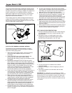
A.
SIDEW
ALL VENTING - NON-DIRECT VENT
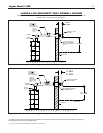
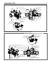
Figures 6 and 7 show typical horizontal sidewall venting. For
combustible wall passage of vent piping, a UL listed thimble
or flashing and sealing boot must be used, providing the wall
thickness from 3" minimum up to 14" maximum. The vent
piping must terminate with a screened tee or elbow termination
facing down.
CA
UTION
:
Flue gasses e
xiting from the v
ent ter
minal will
condense
. Building materials in the area of the vent terminal
should be protected from discoloration and degradation.
V
ENT TERMINATION LOCATION AND CLEARANCES
1
. The venting system shall terminate at least 3 feet above
any forced air inlet located within 10 feet.
2
. The venting system shall terminate at least 4 feet below,
4 feet horizontally from, or 1 foot above any door, window
or gravity air inlet into any building. The bottom of the vent
terminal or air intake terminal shall be at least 12 inches
a
bove grade or the normal snow level whichever is
greater.
3. Through the wall vents shall not terminate over public
walkways or over areas where condensate or vapor could
create a nuisance or hazard or could be detrimental to
the operation of regulators, relief valves or other equip-
ment. Minimum clearance of 4 feet horizontal distance is
maintained, from electric meters, gas meters, regulators
and relief equipment.
4. Vent termination must not be located in any confined
space (i.e. window wells, alcoves, narrow alleys) or under
any overhang or deck. Vent termination should not allow
flue gas discharge towards neighbor’s windows or where
personal injury or property damages can occur.
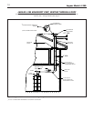
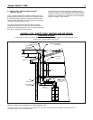
B. NON-DIRECT VENT - VERTICAL VENTING
Figure 8 shows typical venting through the roof. The vent pipe
must pass through the ceiling, floor and the roof vertically
through a 8" minimum diameter cutout. A fire stop is required
for each ceiling and floor penetration. For roof passage, an
appropriate UL listed roof flashing must be used.
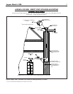
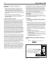
An existing chimney (see Figure 9) may be used as a chase for
vertical venting. Other appliances CANNOT be vented into the
same chimney or vent pipe with in the chimney.
The vertical vent piping must terminate with a screened tee,
combination of 45˚ elbow and a 90˚ screened elbo
w termina-
tion or a rain cap termination.
II. Direct Vent Installation
Air intake piping from outside to the boiler air intake adapter
provides the air for combustion. The boiler surrounding may be
contaminated (See page 5).
Piping the air intak
e to the outside
can prev
ent contaminants from the boiler surrounding from
entering the combustion air supply.
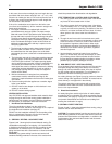
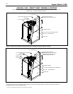
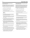
A. SIDEWALL DIRECT VENTING
Figures 10 and 11 sho
w typical side
w
all direct venting, using a
Slant/Fin vent/air intake termination.
CAUTION: Flue gasses existing from the vent terminal will con-
dense. Building materials in the area of the terminal should be
protected from discolor
ation and degradation, in addition to the
requirements of the vent termination location and clearances
stated in this manual.