


Jaguar Model J-390
16
VENTING AND AIR INTAKE SYSTEM REGULAR
INSPECTION
A. Inspect the system regularly for condensation, corrosion,
sagging and/or physical damage. A qualified professional
should service the boiler annually and include such an
i
nspection at that time. The homeowner should look over the
system monthly for damage, water stains, any signs of rust,
other corrosions or separation of the vent and air intake piping
(if direct-vent).
B. Should an inspection turn up signs of condensation,
corrosion, sagging or damage, the boiler should be shut down
immediately and the condition should be corrected by a
qualified professional.
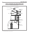
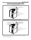
CONDENSATE REMOVAL SYSTEM
The J
aguar J-390 boiler is equipped with a built-in condensation
drain and trap system. This system consists of two traps, one
being dedicated to the condensate produced by the boiler, and
another being dedicated to the condensate produced within the
vent piping. (See page 13 for the location of each of the traps).
Both of these traps must be filled with water. This is most easily
accomplished by pouring water from a small container into the
vent connector at the top of the boiler, before the vent pipe is
attached, until the tubing loop trap in the rear of the boiler is visi-
bly filled. DO NOT operate the boiler without filling the trap with
water to prevent flue gas discharge into space. Periodic inspection
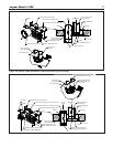
should be made of this assembly for deterioration of the tubing
and components, and to insure that the traps are not plugged. If
any part is plugged or appears to have excessive sediment within,
it should be removed from the drain assembly, have the obstruc-
tion cleared, refilled with water and reinstalled as before.
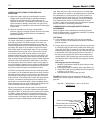
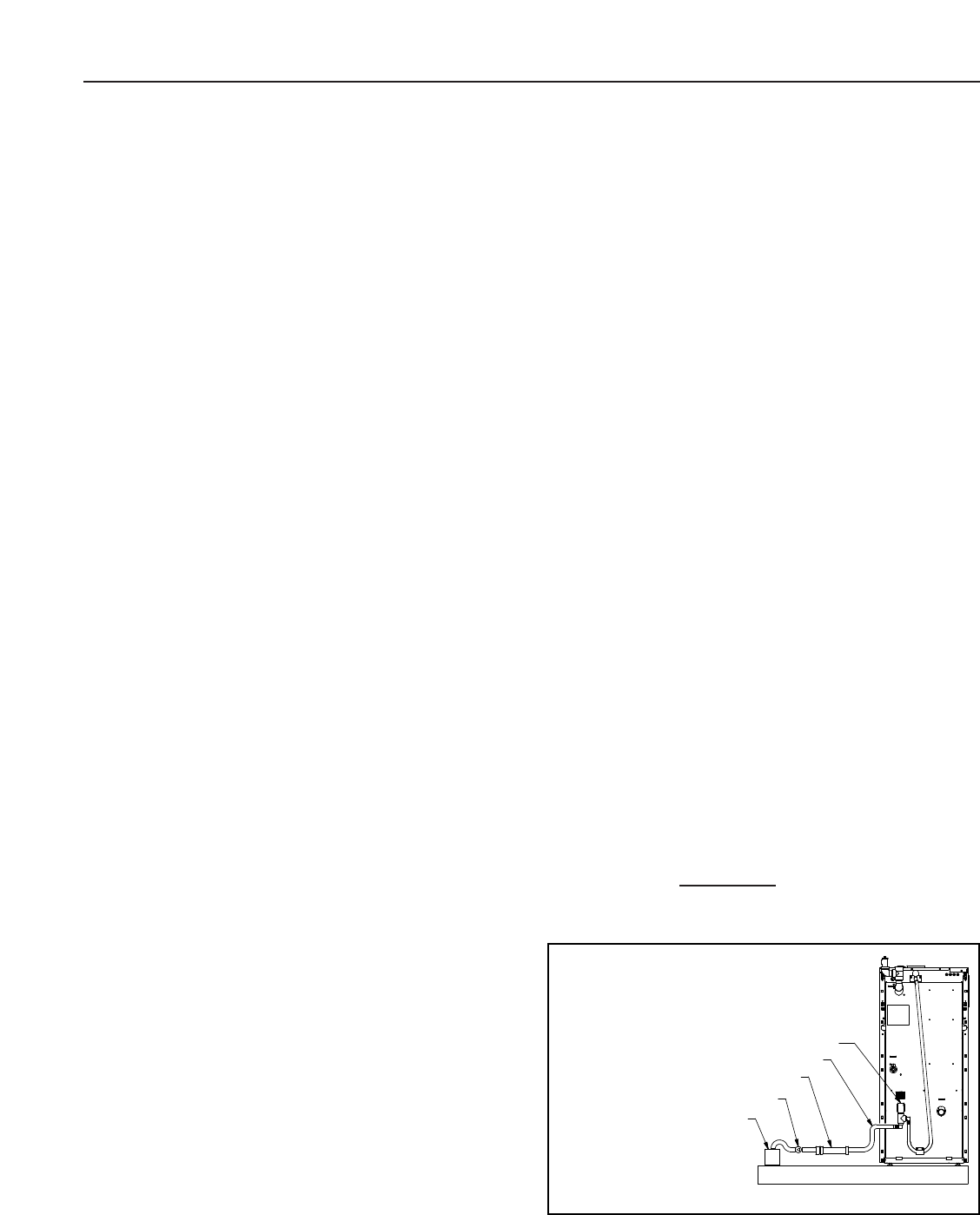
A 3/4” PVC tee assembly, located in the rear of the boiler jacket,
is provided to run the condensate liquid from the boiler. Connect
the plastic tubing that will be run to the drain to the bottom take-
off of the tee. Leave the top take-off of the tee open, to act as a
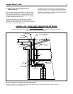
vacuum breaker. If the building drain is above the bottom portion
of the tee, a condensate removal pump will be required. This
pump must have an overflow switch, and be compatible with the
acidic condensate liquid, as must all fittings and the tubing used
in this condensate removal system. (See Figure 14).
No part of the condensate removal system can be exposed to
freezing temperatures, or any other conditions that could cause
blockage. DO NOT run drain tubing to the outside of the building.
In addition, certain jurisdictions or drain pipe materials may
require a neutralization unit to be installed in the condensate
removal system. Any piping other than plastic types will be
subject to corrosion or deter
ioration from the acidic conden
sate, which may have a pH level as low as 3.0. A condensate
filter containing lime, marble, or phosphate chips can neutralize
the condensate to a pH level above 6.5, which is safe for all
drain piping materials. (See Figure 14). The neutralizing filter
medium will require periodic changing, to ensure it’s affective-
ness. Replacing the medium on an annual basis is recom-
mended, or refer to the manufacturer’s instructions for systems
t
hat are available for neutralizing condensate.
COMMONWEALTH OF MASSACHUSETTS SPECIAL
REQUIREMENT
When the Jaguar J-390 is installed and used in the Common-
wealth of Massachusetts, a neutralization unit MUST be installed
in the condensate removal system.
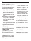
GAS PIPING
A. Local installation codes apply. The pipe joint compound
used on threads must be resistant to the action of liquefied
petroleum gases.
B. T
he gas supply line to the boiler should run directly from the meter
A manual gas supply shut-off valve is provided on the boiler’s gas
supply pipe. (See Figure 2, on page 3). Local codes may specify a
manual main gas supply shut-off valve to be 5’ above the floor, and
a disconnection union at the gas piping entrance to the boiler. In
this case, the gas supply shut-off valve must be relocated to the
specified location. If the gas supply pipe must be upsized for flow
considerations, then the same size main gas supply shut-off valve
must be used.
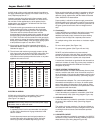
Selecting pipe size for natural gas:
1. Measure or estimate the length of piping from the meter
to the installation site.
2. Consult gas supplier for heating value of gas (Btu/cu. ft.).
3. Divide boiler rated input by heating value to find gas flow
in piping (cu. ft. per hour).
4. Use table below to select proper pipe size.
EXAMPLE: Distance from gas meter to the boiler is 30ft.
Heating value of natural gas is 1020 Btu/cu. Ft. Select proper
pipe size.
Gas flow = 390,000 Btu/hr
= 382 cu. ft. per hour
1020 Btu/cu. ft.
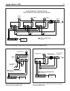
NEUTRALIZING UNIT (IF REQUIRED)
CONDENSATE PUMP (IF REQUIRED)
DRAIN INSIDE BUILDING
PLASTIC TUBING
DRAIN VACUUM BREAKER, LEAVE OPEN
Figure 14. Condensate disposal system