


Jaguar Model J-390
7
T
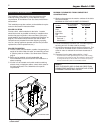
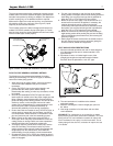
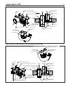
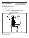
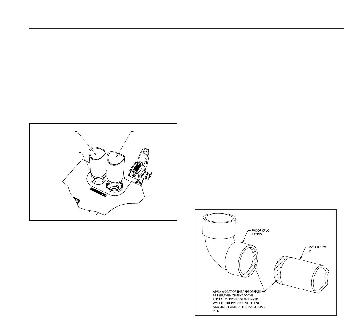
he vent connector on the boiler is designed to directly accom-
modate either PVC/CPVC Schedule 40 pipe or the listed stain-
less steel vent systems by utilizing an adapter. The adapter has
a built-in sealing ring, so no additional sealant is required.
M
ake sure the pipes are round and burr-free, and push down
fully past the sealing ring, until snug. (See Figure 4). Liquid
soap may be used to ease insertion.
T
he air intake collar on the boiler is designed to directly acco-
modate PVC/CPVC schedule 40 pipe (See figure 4). A small
bead of silicon should be applied between the collar and inside
of the air antake pipe, to seal properly.
PVC/CPVC PIPE GENERAL ASSEMBLY METHOD
The following are the recommended methods for cutting,
cleaning and connecting PVC and CPVC pipe, for both the
vent and air intake piping system:
1. When laying out the piping system, work from the boiler
vent and air intake adapter to the point of outside
termination.
2. Cut the PVC/CPVC pipe to the required lengths, and
pre-assemb
le the entire system, bef
ore sealing.
Disassembly after sealing, to make any corrections, will not
be possible
.
3. Once the pre-assembled PVC/CPVC pipe vent and air
intake system is verified to be of the proper length pipe and
fitting orientation, begin disassembling and preparing the
pipes and fittings for the sealing process. This can be done
section by section, or the complete vent and air intake
system can be disassemb
led. It is recommended to mark
the various parts, before complete disassembly, to
eliminate the possibility of errors during re-assembly.
4. De-b
urr the inside and outside of e
v
er
y PVC/CPVC pipe, to
ensure that the
y engage fully into the fittings, and flow is
not compromised. A small chamfer on the outside of each
pipe can particularly aid in the final assembly process.
5. Wipe or knock out any debris from inside the PVC or
CPVC pipe, which may have accumulated there from the
cutting process or stor
age. Debris can cause operational
problems with the boiler combustion components.
6. Thoroughly clean the outside ends of each pipe, and the
inside of each fitting.
The surf
aces m
ust be dr
y for the
sealing agents to w
or
k properly. Handle the prepared pipe
lengths a
way from the cleaned ends, and handle the
cleaned fittings, from the outside, to avoid contamination.
7. Re-assembly of the PVC or CPVC pipe should be done in
sections, to avoid the primer and cement drying before the
parts are engaged.
8
. For each joint, first apply a coat of primer to the outside
s
ealing surface of the pipe and the inside sealing surface of
each fitting. Use only the primer type that is specified for
either the PVC or CPVC pipe that is bing utilized.
9. Before the primer dries, apply a coat of cement over it. A
second coat of cement can be applied, if necessary, but
must be done quickly and in a manner that avoids
unnecessary build-up that would cause obstruction inside
the system. Use only the cement type that is specified for
e
ither the PVC or CPVC pipe that is being utilized.
1
0. Before the cement dries, insert the pipe into the fitting. A
slight twisting motion while pushing the pipe into the fitting
will aid in distributing the cement evenly and ensuring the
parts fully engage.
11. Quickly wipe the excess cement from the outside areas of
the joint. Discard any rags used to avoid later getting the
cement on hands, clothes and equipment.
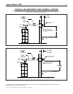
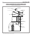
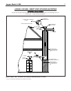
VENT AND AIR INTAKE RESTRICTIONS
1. Maximum allowed equivalent vent and air intake length for
all of the approved vent and air intake materials is 100
equivalent feet.
2. Equivalent of vent or air intake length is sum of the
straight pipe lengths and equivalent length of elbows.
Each 90˚ elbow is equivalent to 10 ft. of 4" pipe.
3. The vent termination is in addition to the allowed
equivalent lengths.
4. Minimum vent length is 2 feet of straight pipe, plus one
90˚ elbow.
5. Vent length restriction is for both direct and non-direct
vent installations.
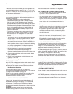
EXAMPLE: The combustion air is provided by air intake
piping directly to the boiler (direct-vent installation). The vent
piping will be PVC and installation location will require the
use of 4 elbows for the vent to run the termination. The air
intake piping will also be PVC, and also will require the use
of 4 elbows.
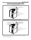
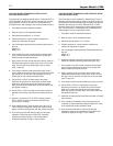
Figure 5.
4" PVC OR CPVC
AIR INTAKE PIPE
AIR INTAKE COLLAR
4" PVC OR CPVC
VENT PIPE
Figure 4. Vent & Air Intake Pipe installation into Boiler Adapter.