


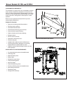
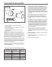
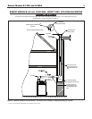
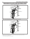
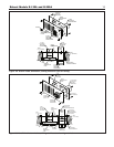

Bobcat Models B-120A and B-200A
6
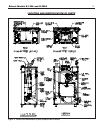
MOUNTING THE BOILER ON A WALL
Be sure that the wall is vertically plumb and capable of carrying
the weight of the boiler and the system piping, when full of
water. See page 2 for the boiler weight.
B
e sure that there are studs available in the proper locations,
for securing the boiler wall bracket and back panel.
(See Figures 4a and 4b).
For wood stud walls, use lag screws or wood screws with a
coarse thread and a minimum of 3” in length.
For metal stud walls, use toggle-style bolts that are specifically
d
esigned for such and maximum capacity exceeds the weight
of the boiler and the system piping when full of water.
DO NOT use anchors driven into sheetrock to hold the boiler
up on the wall. If mounting the boiler on a cement wall, use
anchors that are specifically designed for such, and maximum
capacity exceeds the weight of the boiler and the system
piping, when full of water.
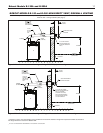
A. INSTALL THE WALL BRACKET. SEE FIGURE 4a.
1. Remove the wall bracket from the boiler jacket rear panel,
by unfastening the single screw that holds it in place, for
shipping purposes only.
2. Select the location on the wall where the boiler will be
mounted. The upward facing tabs of the wall bracket will
align with the top surface of the boiler jacket, and 3 feet of
open wall space will be needed to accommodate the boiler
jacket rear panel below this.
3. For sheetrock and stud construction, locate the studs and
determine which set of holes in the wall bracket best align
with the center of the studs. For cement walls, determine
a location for the wall bracket to mount where the anchors
will be secure, devoid of seams or cracks.
4. Place the bracket in the selected location, with the 2 tabs
positioned up and facing outward, level it out, and mark
the holes to be used. A minimum of 4 of these holes must
be utilized, regardless of w
all material.
5. Drill the appropriate diameter and depth holes for the
fasteners used in the wall, where marked.
6. Fasten the wall bracket to the wall, being sure that the
tabs face upward and outward, and the fasteners have
engaged the w
all proper
ly.
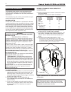
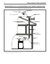
B. INSTALL THE BOILER ON THE WALL. SEE FIGURE 4b.
1. Remove the boiler jacket front cover, by turning the 2 black
screws 1/4 turn to the open position, then lifting off.
2. Remove both the boiler jacket side panels, by removing
the 2 sheetmetal screws in the top and bottom front edge,
then lift off.
3. To aid in lifting the boiler, a 3 foot long, 1/2” inside diameter
steel pipe can be slid through the holes in the sides of the
boiler rear panel. Let the pipe extend out each side of the
jacket evenly, for hand-holds, and pick up the boiler without
letting it tilt, for safety.
4
. Lift the boiler up against the wall, with the top edge of the
j
acket slightly above the wall bracket tabs.There are 2
holes in the upper corners of the jacket rear panel, that
can visually be aligned with the 2 larger diameter holes in
the wall bracket, to ensure that the wall bracket tabs line
up and engage with the boiler jacket near top lip notches
properly.
5
. There are 2 fastener holes in the lower area of the boiler
r
ear panel, just below the flue collector, for insuring the
b
oiler does not move off the wall bracket. Mark these 2
holes, with the boiler in place, then lift the boiler off the wall
bracket.
6. Determine which fastener type will best engage with the
wall construction at the location of the 2 market holes. Drill
out the appropriate diameter and depth holes for the
fasteners, where marked.
7. Lift the boiler up onto the wall bracket again, as described
in Step 4. Secure the boiler to the wall, with the 2 fasteners
in the lower rear panel area.
8. If able to, the 1/2” diameter lifting pipe should be removed
from the boiler rear panel.
9. The 4 boiler legs may be removed at this time, if desired. 2
screws hold each leg in place, from inside the jacket
panel.
10. The boiler side panels can be replaced at this time, but the
front panel should be left off, for the startup procedure
later in the installation.
VENTING APPLICATION
The Bobcat B-120 and B-200 are sealed combustion type
boilers, they may be installed and vented either as a direct vent
boiler which all air for combustion is obtained directly from out-
side or as a non-direct vent boiler which air for combustion is
taken from inside the boiler room.
The Bobcat B-120 and B-200 boilers must be vented by 3"
diameter PVC/CPVC schedule 40 pipe, or the proper 3” diame-
ter stainless steel venting system (see “vent material” on page
7) through the roof or sidewall.
BOILER ROOM AIR SUPPLY AND VENTILATION
An ample supply of air is required for combustion and ventila-
tion. When buildings are insulated, caulked and weather-
stripped, now or later on, direct openings to outside may be
required and should be provided. If the boiler is not near an
outside wall, air may be ducted to it from outside wall openings.
Provisions for combustion and ventilation air must be made in
accordance with section 5.3, Air for Combustion and Ventila-
tion, of the National Fuel Gas Code, ANSI Z223.1-latest edi
-
tion, or applicable provisions of the local building codes. The
following recommendation applies to buildings of energy-saving
construction, fully caulked and weatherstripped.
INSTALLATION IN ENCLOSED BOILER ROOM REQUIRES
TW
O UNOBSTRUCTED OPENINGS FOR PASSAGE OF AIR
INTO THE BOILER ROOM: