


Bobcat Models B-120A and B-200A
37
IV. CHECK COMBUSTION AND FUEL INPUT RATE
A. Remove the boiler jacket front panel, by turning the 2
black screws 1/4 turn to the open position. Lift off panel.
B
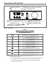
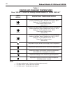
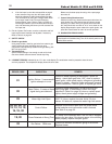
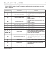
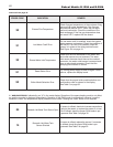
. Start and run the burner at the high firing rate, by using the
“System Test” mode in the “View and changing system
setting” menu. Refer to Table 5 on page 32.
1. Measure the CO, and CO
2
of the flue gas. A
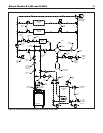
flue sample port is provided in the vent pipe (See
Figure 2 on page 3). The CO should not exceed 100
ppm, when the combustion is correct.The CO2
s
hould be in the range listed in Table 6.
2. If the CO
2
is not within the range specified for that
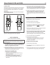
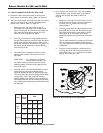
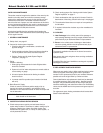
gas type at the high firing rate, then adjust the venturi
throttle to the nominal value shown in Table 6. Turn
the throttle clockwise to decrease the CO
2
value.Turn
the throttle counter-clockwise to increase the CO
2
value. See Figure 26.
3. Once the correct combustion is confirmed at the
high firing rate, check the fuel input rate on the
gas meter.
BTUH INPUT = cu. ft. metered in 3 minutes x
heating value of the gas* x 20
* The higher heating value of the gas can vary for
different localities. Consult the gas supplier for this
value in BTU/cu.ft.
4. If the fuel input is not at the rate specified on page 2
at the high firing rate, then the blower speed
should be adjusted to attain the specified input rate.
This can be done by using the “Change blower RPM
for high input” mode in the “View and changing
System Setting” menu. Refer to Table 5 on page 32.
Increasing the blower rpm will increase the fuel input
rate, and decreasing the blower rpm will decrease the
fuel input r
ate.
C. In the “System Test” mode in the “View and Changing
System Setting” menu, use the “down” push button to
switch to the low firing rate. Refer to Table 5 on
page 32.
1. Measure the CO and CO
2
of the flue gas.The CO
s
hould not exceed 30 ppm, when the combustion
i
s correct. The CO
2
s
hould be in the range
l
isted in Table 6.
2. If the CO
2
is not within the range specified for that
gas type at the low firing rate, then adjust the gas
valve offset to the nominal valve shown in Table 6.
(See Figure 26) for the location of the offset
adjustment. Remove the cap that covers the offset
screw.
Turn the offset clockwise to increase the CO
2
value.
Turn the offset counter-clockwise to decrease the
CO
2
value. Replace the offset cap when adjustment
is complete
.
3. Once the correct combustion is confirmed at the
low firing rate, check the fuel input rate of the gas
meter. BTUH Input = cu. ft. metered in 3 minutes x
heating valve of the gas * x 20.
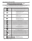
Fuel
Firing
Rate
CO
2
min. nom. max.
Nat.
Gas
High 8.7% 9.0% 9.3%
Low 7.7% 8.0% 8.3%
Propane
High 10.2% 10.5% 10.8%
Low 9.2% 9.5% 9.8%
Table 6. Combustion values for Natural Gas and Propane.
Figure 26. Gas valve and venturi adjustment.