


Bobcat Models B-120A and B-200A
30
OPERATING INSTRUCTIONS
I. FILLING AND VENTING WATER SYSTEMS
A
. Fill the system with water. Vent or purge of air.
B. Fire the boiler as soon as possible (see following warning
and instructions) and bring water temperature in the
system.
C. Vent air and add water as needed to achieve operating
pressure on boiler gauge. Pressure must be between
a
pproximately 12 psi (cold water) and 25 psi at water
t
emperature setting of high limit control, for boilers
equipped with 30 psi relief valves. Boilers rated for a higher
pressure and equipped with a matching relief valve may
operate at a higher pressure, but no higher than 5 psi
belo
w the relief valve opening pressure.
D. Check for and repair any leaks before placing system in
service.
BEFORE FIRING BOILER, make these checks:
Before firing boiler, review the “Boiler Control and Display
Features” section of this manual. Understanding the features and
programming the applicable parameters is essential for setting up
the boiler to operate properly on the heating system it is installed
on.
1. System is full of water. Air is vented or purged.
2. Relief valve is installed in accordance with ASME Boiler
and Pressure Vessel Code, Section IV.Valve opening is
not closed or reduced in size.
3. Venting is installed according to instructions under “FLUE
GAS VENTING REQUIREMENTS”.
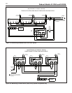
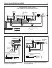
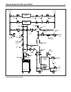
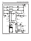
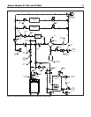
4. All wiring is completed, following applicable wiring
diagrams.
5. Using soap solution, check for gas leaks in all gas piping
from meter to boiler gas supply pipe
.
DO NOT use open
flame.
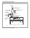
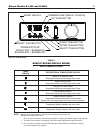
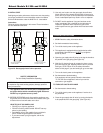
II. BOILER CONTROL AND DISPLAY FEATURES
(See Figure 23)
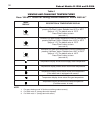
A. Boiler Operation Status:
“Mode Display” shows status of boiler operation
(see table 3).
B
.
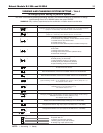
View and Changing Temperatures:
Setting boiler supply w
ater temperature and water tank
temperature (see table 4).
Press “Select” button for viewing following different modes
on “Mode Display”
1. While “c” is blinking, boiler supply water temperature
for space heating may be set to desired temperature
The setting r
ange is betw
een 90˚ to 185˚F
.
2.
While
“d”
is b
linking, boiler supply w
ater temper
ature
for DHW may be set to desired temperature.The
setting range is between 104˚ to 185˚F.
3
. While “t” is blinking, DHW tank temperature may be
s
et to desired temperature (if tank is equipped with
sensor). The setting range is between 104˚ to 185˚F.
4. View actual boiler supply & return water tempera-
ture, domestic hot water tank temperature (if tank
equipped with sensor), flue temperature and outside
temperature (if outside sensor is used) on
“Temperature Display” by selecting 1, 2, 3, 4, or 5 on
“
Mode Display”.
• These numbers are steady on display and are
not settable.
• All sensor inputs to the control must be
connected to a 12k ohm sensor.
C.
Viewing and changing system setting:
A trained, experienced service technician or installer should
perform following adjustments. See table 5 for details.
1. Space heating and DHW post pump time may be
changed.
2. Space heating and DHW modes may be chosen.
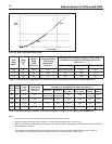
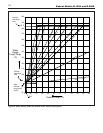
3. Weather compensation slope and set point temperature
may be changed (if outside sensor is used).
(See Figure 24 for graph).
4. Read actual blower RPM
5. Adjust blower RPM for high and low input adjustment.
6. Read flame current in micro amp.
7. Run boiler on high, low or ignition input steady for 20
minutes for test purposes.
D.
Display and push buttons:
1. Reset - Used to clear a Lock out error (indicated with an
“A” in the “Mode Display”).
2.
Select - Used to scroll through the modes in the “View
and Changing Temperatures” and “Viewing and Changing
System Setting” men
us.
3.
Enter - Used to store values that are changed in the “View
and Changing Temperatures” and “Viewing and Changing
System Setting” menus.
4.
Up- Used to increase v
alues in the “View and Changing
Temperatures” and “Viewing and Changing System
Setting” menus.
5.
Do
wn -
Used to decrease v
alues in the “View and
Changing Temperatures” and “Viewing and Changing
System Setting”
men
us
.