


Bobcat Models B-120A and B-200A
19
A
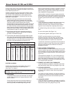
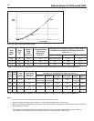
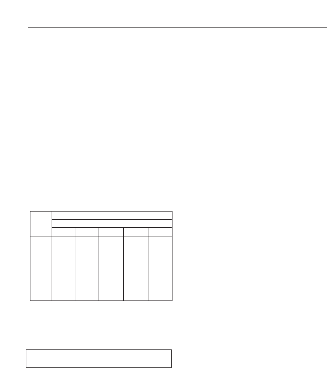
t 30 ft. length of pipe, match required capacity from table on
t
his page (choose higher capacity, in this case is 152 cu. ft. per
hour). Required pipe size is
3
⁄4".
I
mproper gas pipe sizing will result in flame outages, insuffi-
cient heat and other installation difficulties. For more informa-
tion and also if other appliances are to be attached to the
piping system, see Appendix C of National Fuel Gas Code
ANSI Z223.1-latest edition.
C. The boiler and its gas connection must be leak tested
before replacing the boiler in operation. Use liquid soap
solution for all gas leak testing. DO NOT use open flame.
This boiler and it’s individual shutoff valve must be
disconnected from the gas supply piping system during and
pressure testing of that system at test pressures in excess
of
1
⁄2 PSIG.This boiler must be isolated from the gas supply
piping system by closing its individual manual shutoff valve
during any pressure testing of the gas supply piping system
at test pressures equal to or less than
1
⁄2 PSIG.
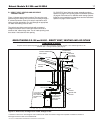
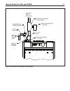
D. All gas piping used should be inspected thoroughly for
cleanliness before makeup. A sediment trap is integrally
provided, as illustrated on page 3.
E. The minimum and maximum gas supply pressure (at the
inlet of gas valve) are shown on the boiler rating plate for
the type of gas used. Gas supply pressure should never be
less than minimum or more than maximum pressure when
the boiler or any other appliance is turned on or off.
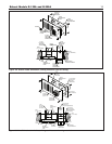
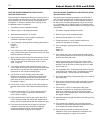
ELECTRICAL WIRING
All field wiring to the boiler is connected to the 2 sets of
ter
minal str
ips, located under the jacket top panel.
(See Figure 2, on page 3)
DANGER: Before wiring always turn off electric power supply.
Otherwise, shock or death can result.
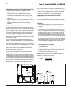
1. Power Supply
A separately fused circuit is recommended. Use standard
15 Amp. fuse or breaker and 14 gage conductors in BX
cab
le or conduit.
Provide disconnect means and overload protection as
required.
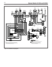
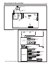
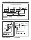
See boiler wir
ing diag
r
am (Figure 16a) boiler
control (Figure16b) and ladder diagram (Figure 16c).
B
oiler must be electrically grounded in accordance with the
r
equirements of the authority having jurisdiction, or, in the
absence of such requirements, with the National Electrical
Code, ANSI/NFPA 70-latest edition.
Proper polarity is critical for the power supply connections.
Reversed polarity will cause system lockout. Proper ground-
ing is critical for boiler operation, connect the ground wire to
the green ground screw next to the line voltage terminal
s
trip.
2. Circulator(s)
A set of terminals are provided for the boiler (primary loop)
circulator. Only wire this circulator to these terminals,
additional (secondary loop) circulators for space heating
require the use of relays and a separate power source.
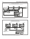
For multiple zoning, either zone valves or circulators maybe
used.
For zone valve system (See Figure 17a).
For pump zoning system (See Figure 17b and 17c).
DO NOT use boiler transformer to power external
accessories like zone valve and relays, overload and/or
burned out transformer and boiler malfunction can result.
Use separate transformer to power such components.
A second set of terminals are provided for the domestic hot
water tank circulator (if used).The primary loop circulator is
always de-energized when the DHW tank circulator is
energized, for priority.
3. SPACE HEATING THERMOSTAT(S)
Install thermostat on an inside wall and away from any heat
sources, sunshine and drafts. A set of terminals are provid-
ed for connection of 24 volt style thermostats, relays or zone
valve end switches (isolated contacts). (See wiring diagram
Figure 16a).
Thermostat heat anticipator: For a non-zoned system set
thermostat heat anticipator to 0.1 Amps, for zoned system
set to match power requirements of zone valves or relays.
Refer to man
ufacturer’
s instructions and specifications. Also
see instr
uctions with ther
mostat.
4. DOMESTIC HOT WATER TANK THERMOSTAT
A set of terminals are provided for connection of the DHW
tank thermostat (if used). (See wiring diagram Figure 16a).
5. OUTDOOR AIR SENSOR
A set of terminals are provided for connection of an outdoor
air sensor (if this method is used). (See wir
ing diagr
am
Figure 16a).
The outdoor air sensor m
ust be a 12k ohm type
.
Mount on
an outside wall, shielded from direct sunlight or flow of heat
or cooling form other sources. See instructions provided
with sensor.
6. LOW WATER CUTOFF
A set of ter
minals are pro
vided f
or connection of a LWCO. If
this de
vice is used, remove the factory installed jumper from
these terminals. (See wiring diagram Figure 16a).
Length
of pipe
in Feet
1/2
3
/4 11
1
/4
1
1
/2
Gas Flow In piping -- cu. ft. per hr.
Iron Pipe Size (IPS) — inches
10 132 278 520 1050 1600
20 92 190 350 730 1100
30 73 152 285 590 890
40 63 130 245 500 760
50 56 115 215 440 670
60 50 105 195 400 610
70 46 96 180 370 560
80 43 90 170 350 530
90 40 84 160 320 490
100 38 79 150 305 460
At pressure drop of 0.3 in. w
ater
, specific gr
a
vity = 0.6.