


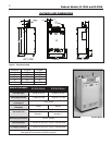

Bobcat Models B-120A and B-200A
10
VENTING INSTALLATION
Only PVC/CPVC and approved stainless steel materials listed
on page 8 may be used for the venting system installation. If
stainless steel vent systems are used, follow the manufactur-
e
r’s instructions, in conjunction with these instructions.
I. Non-Direct Vent Installation
The air for combustion is taken from the ambient air
surrounding the boiler; therefore, ample supply of air is required
for combustion and ventilation (see page 7.)
DO NOT use this installation method if the surrounding of the
boiler is contaminated. See page 5 for the list of harmful
contaminants and their sources, to avoid.
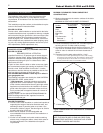
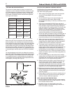
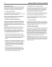
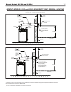
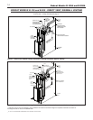
A. SIDEWALL VENTING - NON-DIRECT VENT
Figures 7 and 8 show typical horizontal sidewall venting. For
combustible wall passage of vent piping, a UL listed thimble
or flashing and sealing boot must be used, providing the wall
thickness from 3" minimum up to 12" maximum. The vent
piping must terminate with a screened tee or elbow termination
facing down.
CAUTION: Flue gasses exiting from the vent terminal will
condense. Building materials in the area of the vent terminal
should be protected from discoloration and degradation.
VENT TERMINATION LOCATION AND CLEARANCES
1. The venting system shall terminate at least 3 feet above
any forced air inlet located within 10 feet.
2. The venting system shall terminate at least 12 inches
below or 12 inches horizontally from any door, window
or gravity air inlet into any building. The bottom of the vent
terminal or air intake terminal shall be at least 12 inches
above grade or the normal snow level whichever is
greater.
3. Through the wall vents shall not terminate over public
walkways or over areas where condensate or vapor could
create a nuisance or hazard or could be detrimental to
the operation of regulators, relief valves or other equip-
ment. Minimum clearance of 4 feet horizontal distance is
maintained, from electric meters, gas meters, regulators
and relief equipment.
4. Vent termination must not be located in any confined
space (i.e.
window w
ells
, alco
v
es, narrow alleys) or under
any overhang or deck.Vent termination should not allow
flue gas discharge towards neighbor’s windows or where
personal injury or property damages can occur.
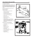
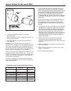
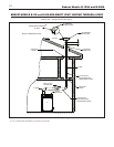
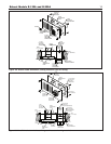
B. NON-DIRECT VENT - VERTICAL VENTING
Figure 9 shows typical venting through the roof.The vent pipe
must pass through the ceiling, floor and the roof vertically
t
hrough a 6" minimum diameter cutout. A fire stop is required
f
or each ceiling and floor penetration. For roof passage, an
appropriate UL listed roof flashing must be used.
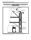
An existing chimney (see Figure 10) may be used as a chase
for vertical venting. Other appliances CANNOT be vented into
the same chimney or vent pipe within the chimney.
The vertical vent piping must terminate with a screened tee,
c
ombination of 45˚ elbow and a 90˚ screened elbow termina-
tion or a rain cap termination.
II. Direct Vent Installation
Air intake piping from outside to the boiler air intake adapter
provides the air for combustion.The boiler surrounding may be
contaminated (See page 5). Piping the air intake to the outside
can prevent contaminants from the boiler surrounding from
entering the combustion air supply.
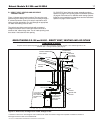
A. SIDEWALL DIRECT VENTING
Figures 11 and 12 show typical sidewall direct venting, using a
Slant/Fin vent/air intake termination. There are 2 different mod-
els of vent/air intake termination available. One is designed
specifically for PVC/CPVC venting, and the other is designed
specifically for stainless steel venting systems. Only these 2
models of vent/air intake termination are approved for this
method of installation. Refer to the Slant/Fin Bobcat B-120 and
B-200 boilers Parts List (publication number B-10PL) for the
appropriate model for the vent material to be used.
CAUTION: Flue gasses existing from the vent terminal will con-
dense. Building materials in the area of the terminal should be
protected from discoloration and degradation, in addition to the
requirements of the vent termination location and clearances
stated in this manual.