


Bobcat Models B-120A and B-200A
16
V
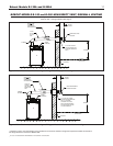
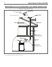
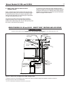
ENT/AIR INTAKE TERMINATION FOR PVC/CPVC
V
ENTING INSTALLATION
This termination is designed specifically for 3” diameter PVC or
CPVC Schedule 40 pipe to be used as the vent and air intake
piping material, only. It can be used on a combustible wall,
provided the 1” minimum clearance of the vent pipe to any
combustible surface is maintained.
1
. Termination must be installed horizontally.
2
. Refer to Figure 13a for installation details.
3. Wall thickness should be 3” to 12” thick.
4. Follow instruction for “vent termination location and
clearances” explained on page 9.
5. Cut a rectangular opening with the following dimensions in
the wall.
Height: 5
1
⁄4”
Width: 12
3
⁄4”
6. From outside of the wall, install outside termination plate
using 4 screws. Make sure the louvers are at left side. Seal
the plate perimeter with silicon.
7. Apply a bead of silicon around the outer surface of the out
side termination plate air intake collar, about 1/2” from the
edge.This will seal the air intake pipe to the air intake
collar, in step #9.
8. From inside, install the inside termination plate, using 4
screws. Make sure that the holes for the vent and air intake
pipe visually line up with the vent passage hole and air
intake collar on the outside termination plate.
9. Cut the PVC or CPVC air intake pipe to the proper
dimension to fit onto the air intake collar of the terminal.
Slide the air intake pipe through the inside termination
plate and onto the air intake collar, where the sealant was
pre-applied in Step #7.
10.
Cut the PVC or CPVC vent pipe so that it will extend out
past the outer surface of the outside termination plate by
2”.
11. Cement a 3” diameter PVC or CPVC coupling onto the
PVC or CPVC vent pipe, and install a stainless steel
screen into the coupling.
12. From outside the wall, insert the bare end of the PVC or
CPVC vent pipe through the outside and inside terminal
plates, until the coupling is flush with the outside wall plate.
13. From inside, proceed with the air intake and vent pipe
installation. Follow the proper PVC/CPVC assembly
pr
actices specified on page 8, and v
enting system
restrictions specified on page 8 of this manual.
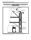
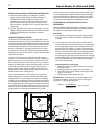
V
ENT/AIR INTAKE TERMINATION FOR STAINLESS STEEL
V
ENTING INSTALLATION
This termination is designed specifically for Heat-Fab Saf-T
vent 3” diameter stainless steel venting system to be used as
the vent, and 3” diameter PVC or CPVC schedule 40 pipe to
be used as the air intake piping material, only. It can be used
on a combustible wall, provided a length of 4” diameter galva-
nized pipe is installed as a thimble around the vent pipe, for the
w
all passage.
1
. Termination must be installed horizontally.
2. Refer to Figure 13b for installation details.
3. Wall thickness should be 3” to 12” thick.
4. Follow instruction for “vent termination location and
clearances” explained on this page.
5. Cut a rectangular opening with the following dimensions in
the wall.
Height: 5
1
⁄4”
Width: 12
3
⁄4”
6. From outside of the wall, install outside termination plate
using 4 scre
ws. Make sure the louvers are at left side. Seal
the plate perimeter with silicon.
7. Apply a bead of silicon around the outer surface of the
outside termination plate air intake collar, about 1/2” from
the edge.This will seal the air intake pipe to the air intake
collar, in step #11.
8. For combustible wall a 4” galvanized pipe must be used as
a wall thimble.The length of the 4” galvanized pipe should
be approximately 1” shorter than the wall thickness.
9. From inside the building, fit galvanized pipe over 4” collar of
the outside plate.
10. From inside, install inside termination plate using 4 screws.
Make sure the 4” collar on the plate, penetrated into the
galv
anized pipe.
11.
Cut the PVC or CPVC air intak
e pipe to the proper
dimension to fit onto the air intake collar of the terminal.
Slide the air intake pipe through the inside termination
plate and onto the air intake collar, where the sealant was
pre-applied in Step #7.
12. Assemble and seal straight screened termination to the slip
joint connector.
13.
F
rom outside of the building, insert vent pipe (slip joint
connector and termination assembly) through the 3” holes
of the outside and inside termination plate.
14. From inside, proceed with air intake and vent pipe
installation. Follow vent manufacturer’s instructions and
restrictions specified on page 8 of this manual.