


Bobcat Models B-120A and B-200A
17
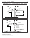
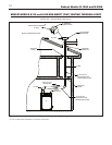
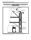
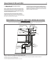
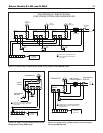
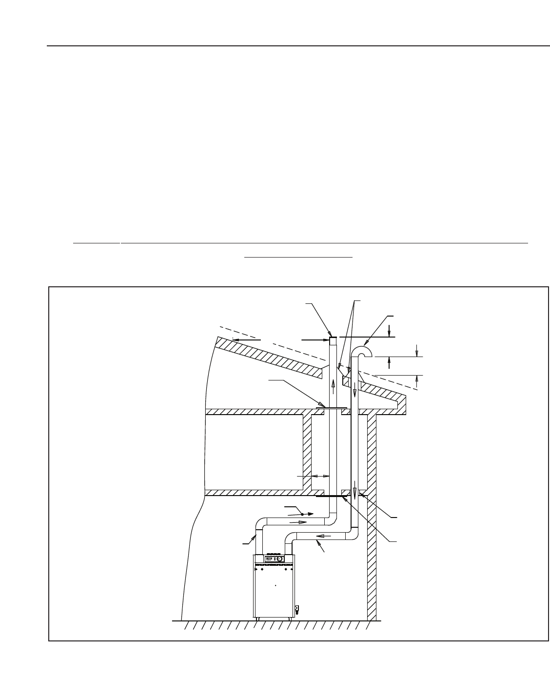
B. DIRECT VENT - VENTING AND AIR INTAKE
THROUGH A ROOF
F
igure 14 shows typical vertical venting.The vent pipe must
p
ass through the ceiling, floor and the roof vertically through a
6” minimum diameter cutout. A fire stop is required for each
ceiling and floor penetration. For roof passage an appropriate
UL listed roof flashing must be used.
The vertical vent piping must terminate with a screened
straight termination. The air intake termination should be a
screened 180˚ elbow facing down. The air intake opening must
b
e at least 1 foot below the vent opening.
F
or PVC/CPVC pipe, follow the proper assembly practices
s
pecified on page 8, and venting system restrictions specified
on page 8 of this manual. For stainless steel venting systems,
follow the vent manufacturer’s instructions and the restrictions
specified on page 8 of this manual
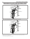
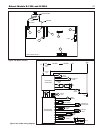
BOBCAT MODELS B-120 and B-200 - DIRECT VENT, VENTING AND AIR INTAKE
THROUGH A ROOF
All joints must be liquid and pressure tight. Use 3” dia. PVC/CPVC schedule 40 pipe or U/L listed single wall 3" dia.
AL29-4C S.S.*. venting materials (See page 7).
SNO
W L
INE
1 FT.MIN.
1 FT.MIN.
STRAIGHT TERMINATION
WITH SCREEN
10 FT. MIN
FIRESTOP AND
SUPPORT
2" MIN.
SLOPE UP 1/4 IN.
PER FOOT MIN.
3
"
DIA. PVC/CPVC
OR STAINLESS
STEEL VENTING
MATERIAL FOR
VENT
3
"
DIA.PVC/CPVC
OR STAINLESS
STEEL PIPE FOR
AIR INTAKE
FIRESTOP AND
SUPPORT
PIPE
SUPPORT
FLASHING AND
STORM COLLAR
AIR INTAKE
180˚ ELBOW
WITH SCREEN
Figure 14. Direct vent, venting and air intake through a roof.
*
AL 29-4C IS A REGISTERED TRADEMARK OF ALLEGHENY LUDLUM CORP
.
** Definition of Snow Line: Knowledge of local conditions will reveal the maximum height that repeated snowfalls accumulate to.
The height should be used as the SNOW LINE.