


Troubleshooting & Repair
ii
c:
D.
E.
F.
G.
H.
I.
J.
K.
L.
‘2733
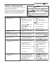
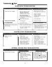
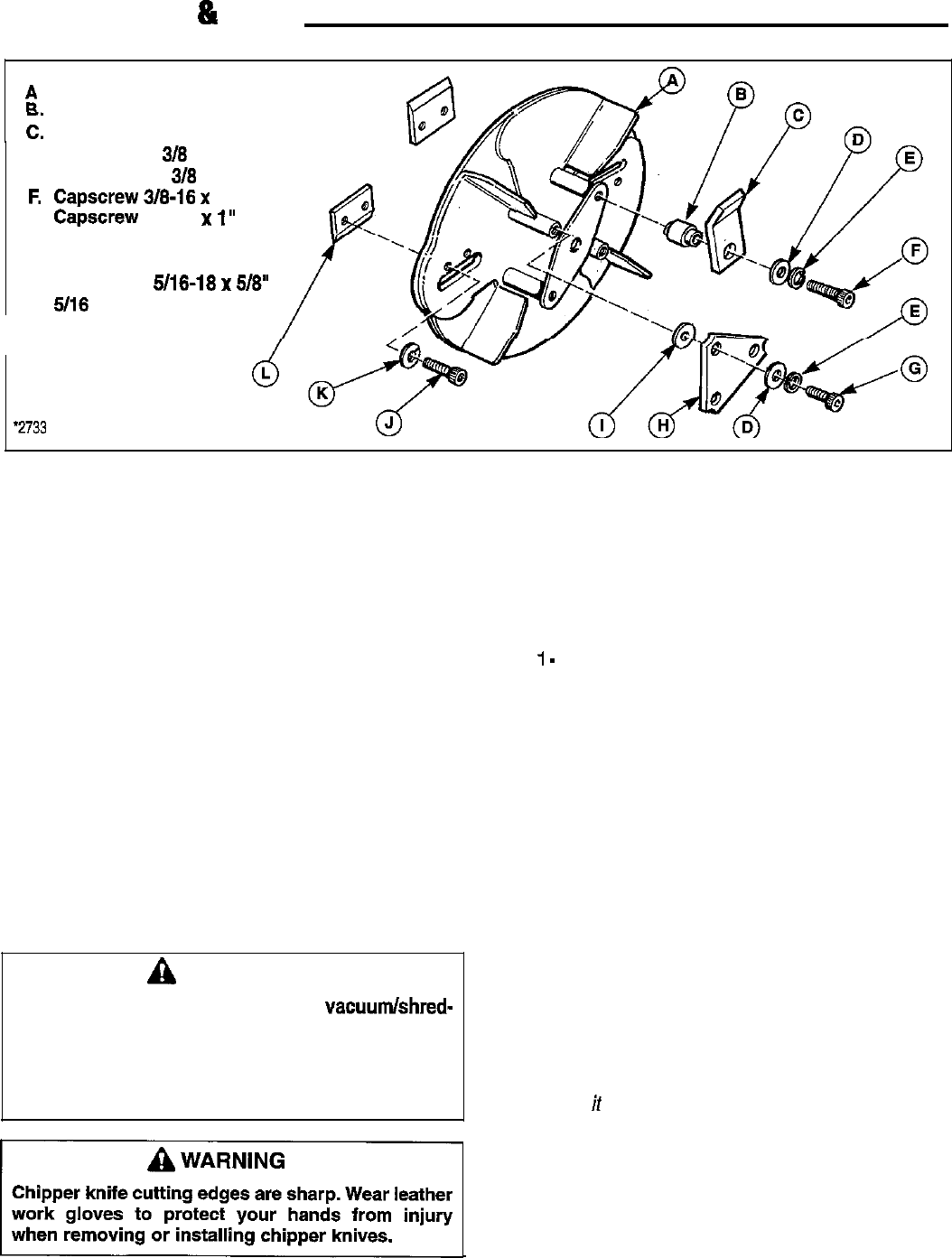
Rotor
Spacer
J Hammer (2)
Flat Washer
318
Lock Washer
310
Capscrew
318-16
x
2”
Capscrew 318-f 6 x 1”
Triangular Hammer (2)
Bushing, Flanged
Cap Screw 5/16-18
x
5/8”
5116
Lock Washer
Chipper Knife (2)
Figure 29. Proper Hammer Assembly
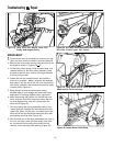
15. Rotate the rotor to move the next hammer into
position for servicing, and repeat step 14.
16. If chipping knives are to be inspected or serviced, go
to the next section for instructions. If service is to be
performed on shredding hammers only, proceed to
the next step.
17. Reassemble the unit in the reverse sequence used
to disassemble it in the preceding steps.
18. Check all hardware for tightness and correct
assembly before attempting to start the unit. Do not
attempt to start the unit if extra hardware or other
parts are left over after reassembly has been
completed. Identify the correct assembly location for
any remaining parts using the illustrations in the
manual, and install as required.
19. Start the unit and listen for unusual noise or vibra-
tion. Stop the unit immediately if any problems are
apparent, and check the assembly of all parts for
proper positioning before starting the unit again.
A
WARNING
Never use the unit for chipping or
vacuumlshred-
ding unless the discharge bag is attached, or the
deflector elbow has been installed.
.
Material could be ejected out of the discharge
chute with great force, injuring you or bystanders.
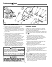
CHIPPING KNIVES
Chipping knives should be resharpened or replaced
when tree limbs and branches begin to require extra
force to feed into the chipper block.
To inspect and service the chipping knives, follow these
steps: (If hammer service has just been performed, skip
steps
1
-
2).
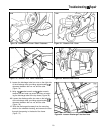
1. Turn the engine off, allow the rotor to stop
completely, and disconnect the spark plug wire.
2. Remove the top and right side covers as shown in
the preceding hammer replacement section.
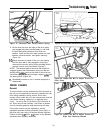
3. Remove the discharge bag.
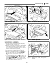
4. Remove the panel fastener and slotted hex head
screws from the left cover (Figure 29).
5. Remove the left cover (Figure 30).
6. Remove the panel fasteners from the rear panel
(Figure 31).
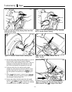
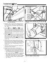
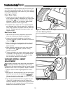
7. Slide the rear panel down, and tilt the rear of the unit
up slightly to allow the panel to slide free of the
grooves in the discharge tube (Figure 33).
7a. Electric start units only: Disconnect and remove the
battery.
NOTE: Always remove the negative terminal cab/e first
and reinstall if last to reduce the risk of sparking and
short-circuiting the battery if metal-to-metal contact is
““““““1
made between the positive terminal and the unit’s frame.
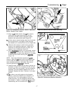
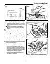
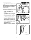
Chipper knife cutting edges are sharp. Wear leather
7b. 8 H.P. units only: Remove top screws securing the
work gloves to protect your hands from injury
fuel tank to the frame, and carefully move fuel tank
when removing or installing chipper knives.
forward and rest it on drive belt while chipper knife
service is being performed.
26