


48 DOCA0005EN-04
Front panel display and meter setup iEM3100 / iEM3200 / iEM3300 series user manual
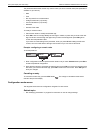
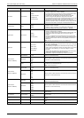
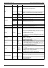
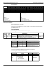
Section Parameter Options Description
Wiring
Type
3PH3W
3PH4W
1PH2W L-N
1PH2W L-L
1PH3W L-L-N
1PH4W Multi L-N
Select the power system type the meter is wired to.
VT
Direct-NoVT
Wye(3VTs)
Delta(2VTs)
Select how many voltage transformers (VT) are connected to the electrical power
system.
CT
3CTs on I1, I2, I3
1 CT on I1
2 CTs on I1, I3
Define how many current transformers (CT) are connected to the meter and which
terminals they are connected to.
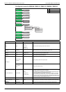
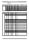
CT & VT Ratio
CT Secondary
1
5
Select the size of the CT secondary, in Amps.
CT Primary 1 - 32767 Enter the size of the CT primary, in Amps.
VT Secondary
100
110
115
120
Select the size of the VT secondary, in Volts.
VT Primary 1 - 1000000 Enter the size of the VT primary, in Volts.
Frequency Frequency
50
60
Select the frequency of the electrical power system, in Hz.
Date Date DD-MMM-YYYY Set the current date using the specified format.
Time Time hh:mm Set the time using the 24-hour format.
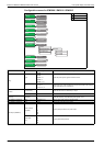
Multi Tariffs Control Mode
Disable
by Communication
by Digital Input
by Internal Clock
Select the tariff control mode:
• Disable: the Multi Tariff function is disabled.
• by Communication: the active tariff is control by communications. See the chapter
for the applicable protocol for more information.
• by Digital Input: the digital input is associated with the multi-tariff function. A signal to
the digital input changes the active tariff.
• by Internal Clock: the device clock controls the active tariff. If you set the Control
Mode to by Internal Clock, you must also configure the schedule. Set the time when
each tariff period starts, using the 24 hour clock format (00:00 to 23:59). The start
time of the next tariff is the end time of the current tariff. For example, T2 start
equals the end of T1.
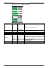
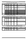
Overload Alarm Alarm
Disable
Enable
Select whether or not the Overload Alarm is enabled:
• Disable: the alarm is disabled.
• Enable: the alarm is enabled. If you enabled the Overload Alarm, you must also
configure the Pick Up Value in kW from 1 - 9999999.
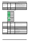
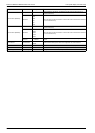
Digital Output DO Function
Disable
for Alarm
for Pulse (kWh)
Select how the digital output functions:
• Disable: the digital output is disabled.
• for Alarm: the digital output is associated with the overload alarm. The meter sends
a pulse to the digital output port when the alarm is triggered.
• for Pulse: The digital output is associated with energy pulsing. When this mode is
selected, you must also configure the can select the energy parameter and the set
the Pulse Constant (imp/kWh) and the Pulse Width (ms).
NOTE: the iEM3275 does not have a digital output.
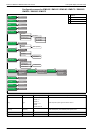
Digital Input DI Function
Input Status
Tariff Control
Input Metering
Partial Reset
Select how the digital input functions:
• Input status: the digital input records the status of the input, for example, OF, SD of
a circuit breaker.
• Input Metering: the digital input is associated with input metering. The meter counts
and records the number of incoming pulses. If you set the DI Function to Input
Metering, you must also configure In. Pulse Constant.
• Tariff Control: the digital input is associated with the multi-tariff function. A signal to
the digital input changes the active tariff.
• Partial Reset: a signal to the digital input initiates a partial reset.
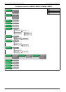
Communication (iEM3255)
Slave Address 1 - 247
Set the address for this device. The address must be unique for each device in a
communications loop.
Baud Rate
19200
38400
9600
Select the speed for data transmission. The baud rate must be the same for all devices
in a communications loop.
Parity
Even
Odd
None
Select None if the parity bit is not used. The parity setting must be the same for all
devices in a communications loop.
NOTE: Number of stop bits = 1.