


84 DOCA0005EN-04
Communications via M-Bus iEM3100 / iEM3200 / iEM3300 series user manual
Communications setup
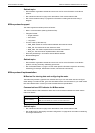
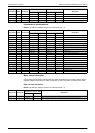
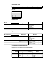
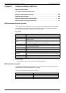
To change the baud rate via communications, send a telegram to the meter with the appropriate value
in the CI-field:
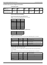
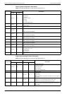
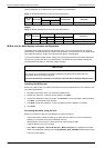
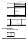
Digital input setup
NOTE: E denotes the extension bit; the hex value assumes E = 0.
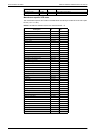
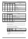
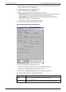
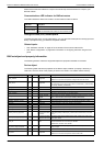
Digital output setup
NOTE: E denotes the extension bit; the hex value assumes E = 0.
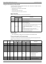
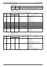
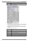
Overload alarm setup and acknowledgment
Use the information in the table below to configure the overload alarm.
NOTE: E denotes the extension bit; the hex value assumes E = 0.
SND_UD code Data format Primary VIF Range/options Description
00 01 7A 0-250 Primary address
Baud rate Hex value for CI-field
300 B8
600 B9
1200 BA
2400 BB
4800 BC
9600 BD
SND_UD
code
Data format
Manufacturer-specific VIFE
Range/options Description
bin hex
00 02 E001 1011 1B 0, 3, 5
Digital input control mode
0 = Normal (Input Status)
3 = Input metering
5 = Partial energy reset
00 05 E010 1111 2F 1-10000
Pulse constant (pulses/unit; applicable when the digital
input is used for input metering)
SND_UD
code
Data format
Manufacturer-specific VIFE
Range/options Description
bin hex
00 02 E001 1010 1A 2, 3, 0xFFFF
Digital output control mode
2 = Alarm
3 = Energy (energy pulsing)
0xFFFF = Disable
00 05 E010 1110 2E
iEM3135 / iEM3335: 1, 10, 20, 100,
200, 1000
iEM3235: 0.01, 0.1, 1, 10, 100, 500
Pulse constant
NOTE: This information only applies if the digital output
control mode is set to for Pulse.
00 02 E010 1100 2C 50, 100, 200, 300
Pulse width in ms
NOTE: This information only applies if the digital output
control mode is set to for Pulse.
SND_UD
code
Data format
Manufacturer-specific VIFE
Range/options Description
bin hex
00 05 E011 0101 35 0 - 9999999
The pickup setpoint in kW for the
overload alarm
00 02 E011 0100 34 0,1
Overload alarm setup:
0 = Disable
1 = Enable