12 NTE/CCD Detector Manual Version 2.A
suitable Gain setting. In situations where the A/D range exceeds that of the array, it will
generally be better to set the Gain to HI so that the signal can be spread over as much of
the A/D range as possible. This is a particularly important consideration in absorbance
measurements. Users who consistently measure low-level signals may wish to select HI,
which reduces some sources of noise. Users who measure high-level signals may wish to
select LO to allow digitization of larger signals. Customized values of gain can be
provided. Contact the factory for additional information.
Spectroscopy Setup
This section describes how to set up the detector for spectroscopy applications.
Instructions for imaging applications appear later in this chapter. Microscopy
applications are discussed in Chapter 5.
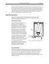
Spectrograph Theory
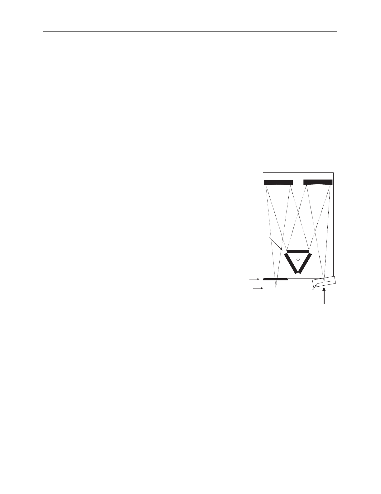
In a typical spectrograph, light enters the
entrance slit and is collected by a
collimating mirror. Essentially, what a
spectrograph does is to form an image of
the entrance slit in the exit focal plane with
each position in the plane representing a
different wavelength. Collimated light
strikes the grating and is dispersed into
individual wavelengths (colors). Each
wavelength leaves the grating at a different
angle and is reimaged by a focusing mirror
onto a CCD detector at the exit focal plane.
As each wavelength images at a different
horizontal position, the spectrum of the
input light is spread across the CCD.
Individual wavelengths focused at different
horizontal positions along the exit port of
the spectrograph are detected
simultaneously. Rotating the diffraction
grating scans wavelengths across the CCD,
allowing the intensity at individual
wavelengths to be easily measured.
Triple
Grating
Turret
Entrance
Slit
CCD Focal Plane
CCD Port
Collimating Mirror
Focusing Mirror
Figure 3. Annotated Spectrograph Drawing
Array Orientation
For spectroscopy, the detector should be mounted so that the short axis of the CCD is
parallel to the entrance slit. The long axis will therefore correspond to the wavelength
axis of the spectrum. Because the NTE/CCD Detector is ordinarily not internally
shuttered in spectroscopy applications, the orientation of the CCD can be readily
determined by visual inspection of the faceplate. The faceplate cutout closely
corresponds to the dimensions of the underlying CCD array, which will itself be visible
through the window.


