Chapter 2
Detector Setup
This chapter covers the setup procedures for both imaging and spectroscopic
applications.
General Instructions
The following items are applicable to both imaging and spectroscopic systems.
Connecting the Detector
Each detector is supplied with a cable to connect to the controller. Make sure that the
controller is off, and then connect the larger end of the cable to the port marked
Detector
on the controller. The detector end of the cable is secured by a slide-lock
latch. The controller end of the cable, depending on the model of controller, is secured
by a slide-lock latch or by screws. Tighten the screws in place.
Controller Internal Switches
Any user who will be running both NTE/CCDs
and
LN/CCDs with an ST-138 controller
must ensure that the internal power supply switches inside the controller are set properly.
Consult the controller manual for instructions on setting these switches. In the case of the
ST-133 Controller there are no internal switches.
Note:
If the system includes an ST-138 that was ordered with the NTE/CCD, the
internal switches will be properly set. These switches are only a consideration if an
already available controller is to be used with both NTE and LN detectors.
Gain Control
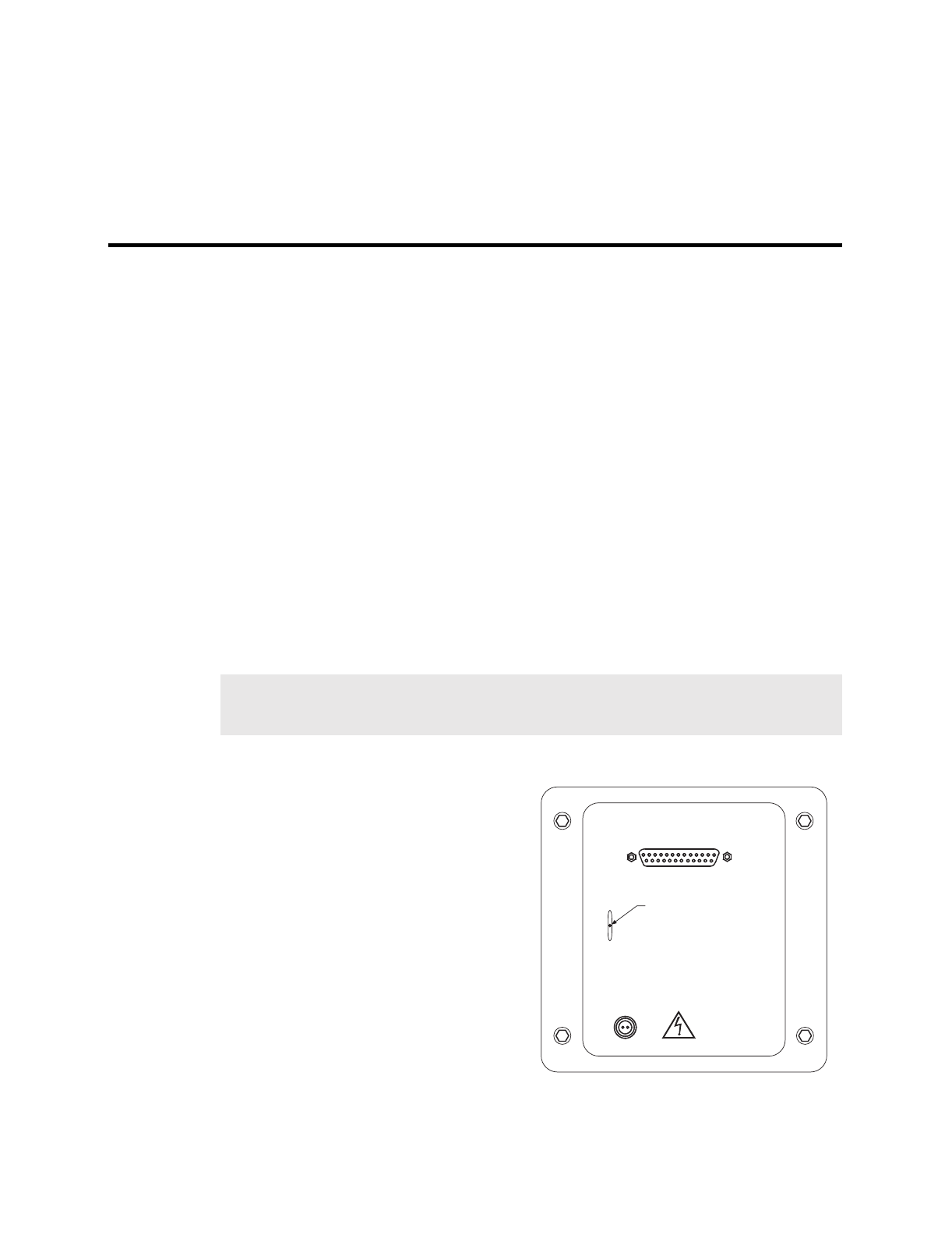
A gain control switch is provided on most
NTE/CCD detectors. This allows the user
to select one of three settings, LO, MED
and HI, which change the detector gain to
0.5×, 1× and 2×. This switch is active
when the detector is being controlled by an
ST-138. If an ST-133 controller is being
used, the switch is deactivated and gain
control is accessed in the software.
The gain of the detector should generally be
set so that the overall noise is ~1 count RMS.
In most instances this will occur with the
switch set to MED. If the array is a 1340 ×
100 or 1340 × 400 configured with the low-
noise output, LO will probably be a more
CONTROLLER
H
M
L
WARNING: DO NOT OPERATE UNIT
WITHOUT PROTECTIVE COVERS.
GAIN
SHUTTER
Gain Control Switch
Figure 2. NTE Detector Rear Panel


