


Regency P33 Sunrise
TM
Gas Fireplace 27
INSTALLATION
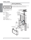
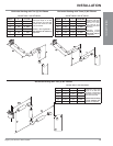
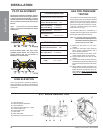
GAS LINE
INSTALLATION
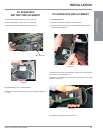
The gas line is brought through the right side
of the appliance. The gas valve is situated on
the right hand side of the unit and the gas inlet
is on the right hand side of the valve.
The gas line connection may be made of
rigid pipe, copper pipe or an approved fl ex
connector. (If you are using rigid pipe, ensure
that the valve can be removed for servicing.)
Since some municipalities have additional
local codes it is always best to consult with
your local authorities and the CAN/CGA B149
installation code.
For USA installations follow local codes and/
or the current National Fuel Gas Code, ANSI
Z223.1.
When using copper or fl ex connectors use only
approved fi ttings. Always provide a union so
that gas lines can be easily disconnected for
servicing. Flare nuts for copper lines and fl ex
connectors are usually considered to meet
this requirement.
Important: Always check for gas leaks
with a soap and water solution or gas leak
detector. Do not use open fl ame for leak
testing.
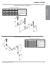
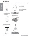
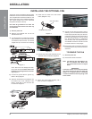
Diagram 4
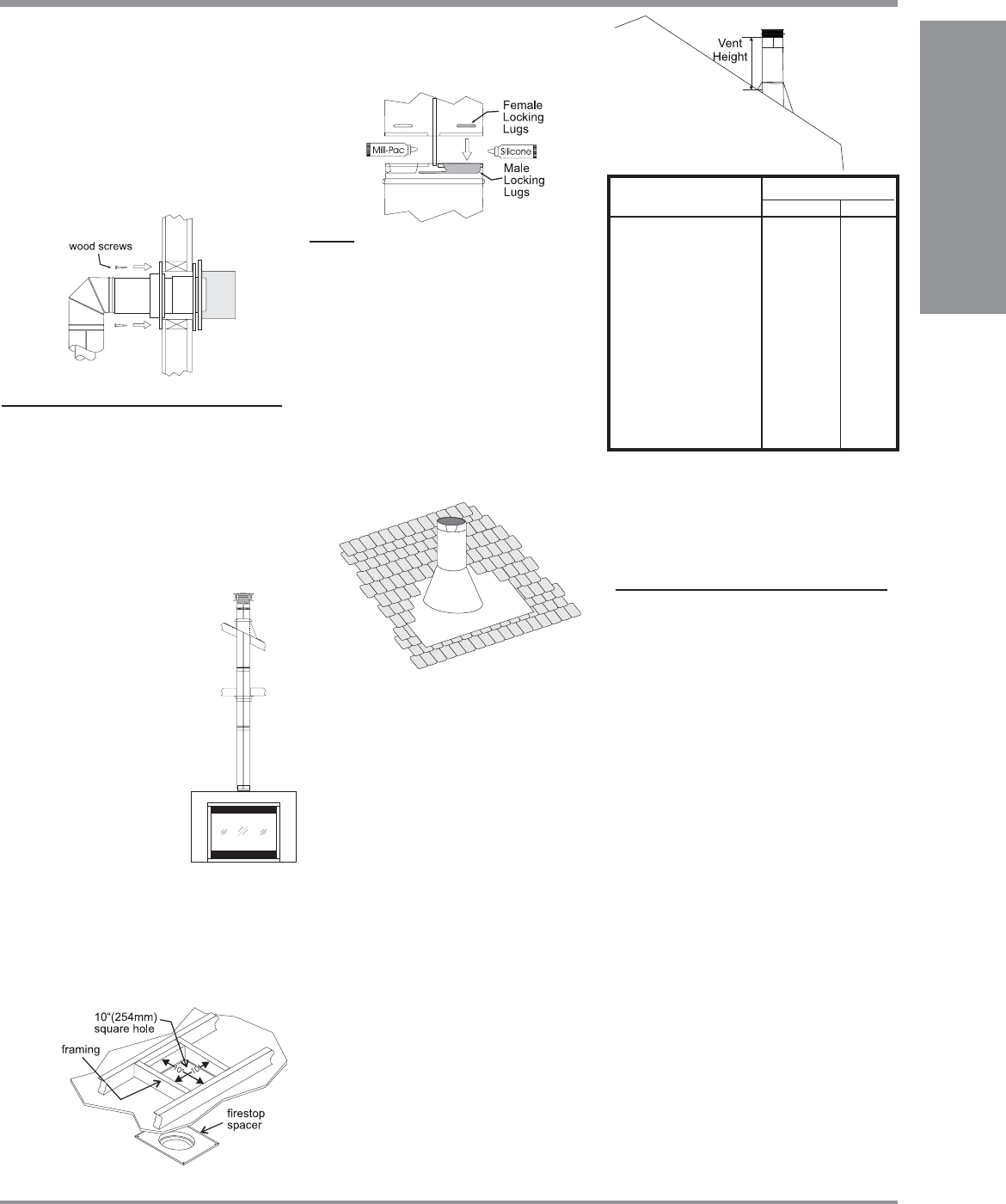
Diagram 3: The upper half of the fl ashing is
installed under the roofi ng material and not
nailed down until the chimney is installed.
This allows for small adjustments.
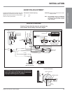
Diagram 2
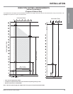
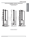
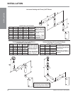
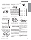
UNIT INSTALLATION
WITH VERTICAL
TERMINATION
1) Maintain the 1-1/2" clearances (air spaces) to
combustibles when passing through ceilings,
walls, roofs, enclosures, attic rafter, or other
nearby combustible surfaces. Do not pack
air spaces with insulation. Check "Venting"
Sections for the maximum
vertical rise of the venting system
and the maximum horizontal
offset limitations.
2) Set the gas appliance in its
desired location. Drop a plumb
bob down from the ceiling to
the position of the appliance
fl ue exit, and mark the location
where the vent will penetrate the
ceiling. Drill a small hole
at this point. Next, drop a
plumb bob from the roof to
the hole previously drilled
in the ceiling, and mark the
spot where the vent will
penetrate the roof.
3) A Firestop spacer must be installed in the
fl oor or ceiling of every level. To install the
Firestop spacer in a fl at ceiling or wall,
cut a 10 inch square hole. Frame the hole
as shown in Diagram 2 and install the
fi restop.
Diagram 4
NOTE: For best results and optimum
performance with each approved venting
system, it is highly recommended to apply
“Mill-Pac” sealant (supplied) to every in-
ner pipe connection. Failure to do so may
result in drafting or performance issues not
covered under warranty. Silicone (red RTV)
is optional.
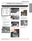
8) Slide the appliance and vent assembly
towards the wall carefully inserting the
vent pipe into the vent cap assembly. It is
important that the vent pipe extends into the
vent cap suffi cient distance so as to result
in a minimum pipe overlap of 1-1/4 inches.
Secure the connection between the vent pipe
and the vent cap 3 sheet metal screws.
9) Install wall thimble in the center of the
10" square and attach with wood screws
(Diagram 4).
4) Assemble the desired lengths of pipe and
elbows. Ensure that all pipes and elbow
connections are in the fully twist-locked
position and sealed.
5) Cut a hole in the roof centered on the small
drilled hole placed in the roof in Step 2. The
hole should be of suffi cient size to meet
the minimum requirements for clearance
to combustibles of 1-1/2". Slip the fl ashing
under the shingles (shingles should overlap
half the fl ashing) as per Diagram 3.
6) Continue to assemble pipe lengths.
Note: If an offset is necessary in the attic to
avoid obstructions, it is important to
support the vent pipe every 3 feet, to
avoid excessive stress on the elbows,
and possible separation. Wall straps
are available for this purpose.
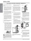
Galvanized pipe is desirable above the roofl ine
due to its higher corrosion resistance. Continue
to add pipe sections through the fl ashing until
the height of the vent cap meets the minimum
height requirements specifi ed in Dia. 4 or local
codes. Note that for steep roof pitches, the
vertical height must be increased. A poor
draft, or down drafting can result from high
wind conditions near big trees or adjoining
roof lines, in these cases, increasing the
vent height may solve the problem.
7) Ensure vent is vertical and secure the base
of the fl ashing to the roof with roofi ng rails,
slide storm collar over the pipe section and
seal with a mastic.
8) Install the vertical termination cap by twist-
locking it.
Note: Any closets or storage spaces, which
the vent passes through must be
enclosed.
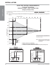
Diagram 1
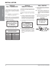
Roof Pitch Minimum Vent Height
Feet Meters
fl at to 7/12 2 0.61
over 7/12 to 8/12 2 0.61
over 8/12 to 9/12 2 0.61
over 9/12 to 10/12 2.5 0.76
over 10/12 to 11/12 3.25 0.99
over 11/12 to 12/12 4 1.22
over 12/12 to 14/12 5 1.52
over 14/12 to 16/12 6 1.83
over 16/12 to 18/12 7 2.13
over 18/12 to 20/12 7.5 2.29
over 20/12 to 21/12 8 2.44
INSTALLATION