


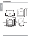
Regency® L676S Direct Vent Gas Fireplace
14
INSTALLATION
INSTALLATION
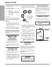
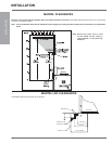
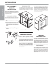
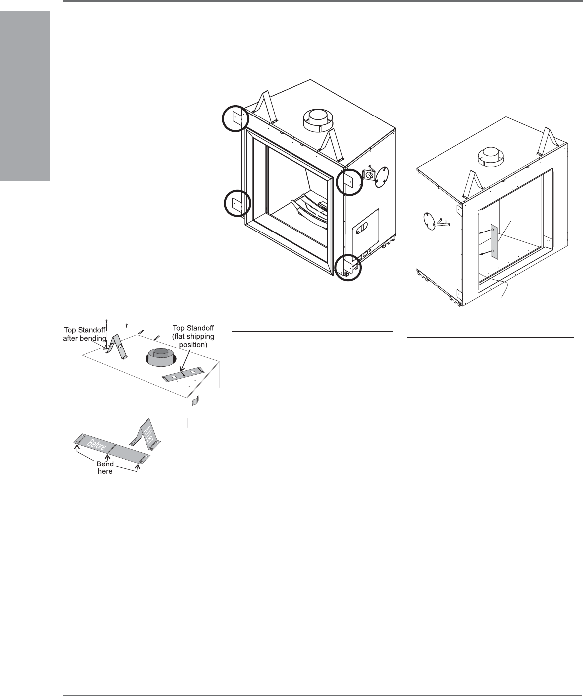
SIDE NAILING STRIPS
The side nailing strips come attached to the unit.
There are 2 plates on each side, one on the top
and bottom that can be folded out as required.
UNIT ASSEMBLY
PRIOR TO
INSTALLATION
The Top Facing Support, the Side Nailing Strips
and the 2 Top Standoffs must be correctly
positioned and attached to the top before unit
is slipped into position.
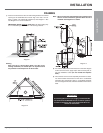
TOP STANDOFF ASSEMBLY
The top standoffs are shipped in a fl at position
and must be folded into shape and attached.
1) Remove the standoffs from the fi replace
top.
2) Take each standoff and bend into the correct
shape. Bend up at the bend lines until the
screw holes in the standoff and the pre-
punched screw holes on the fi replace top
line up.
3) Attach the standoff securely to the top
with 2 screws per standoff (on opposite
corners).
Side Nailing Strips shown folded out.
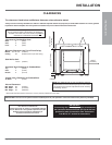
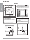
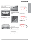
FINISHING TEMPLATE
In order to maintain a clean face; the L676S
allows for a 1/8” in overlap of fi nishing material,
such as rock or tile, on both the left and right
hand sides of the unit (top and bottom sides do
not allow for an overlap), this overlap must not
be exceeded or the glass door will no longer
open properly.
Non-combustible wall board is installed up to the
fl anges on all sides of the unit. When installing
any additional facing material use the Finishing
Template (included with the unit) to ensure
that the fi nishing material does not exceed the
allowable overlap.
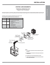
Left Side Flange
Finishing
Template
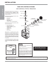
VENTING
INTRODUCTION
The L676S uses the "balanced fl ue" technology
Co Axial system. The inner liner vents products
of combustion to the outside while the outer liner
draws outside combustion air into the combustion
chamber thereby eliminating the need to use
heated room air for combustion and losing warm
room air up the chimney.
Note: These fl ue pipes must not be connected
to any other appliance.
The gas appliance and vent system must be
vented directly to the outside of the building,
and never be attached to a chimney serving a
separate solid fuel or gas burning appliance.
Each direct vent gas appliance must use it's own
separate vent system. Common vent systems
are prohibited.
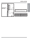
The Finishing Template uses two magnets to
attach itself to the fl ange on the left or right
side of the unit (see diagram below). Install the
facing material up to the outside edge (when
facing the unit) of the fi nishing template. This
template may be discarded after the facing
material has been installed.