


Regency
®
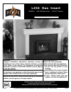
L234 Direct Vent Gas Insert 9
INSTALLATION
INSTALLATION
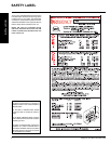
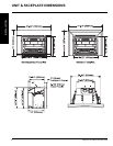
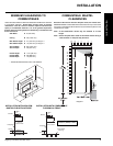
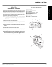
MINIMUM CLEARANCES TO
COMBUSTIBLES
Side Walls A 8" (203 mm)*
Ceiling B 56" (1422 mm)
Min. Mantel Height C 21" (533 mm) see Diagram 1
Max. Mantel Depth D 12" (305 mm) see Diagram 1
Alcove Width E 60" (1524 mm)
Alcove Depth F 36" (914 mm)
Hearth Height G 1-1/2" (38 mm)
Hearth Width H 28" (686 mm)
Hearth Depth I 12" (305 mm)
* Alcove side wall must have a min. of 8" clearance.
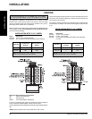
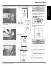
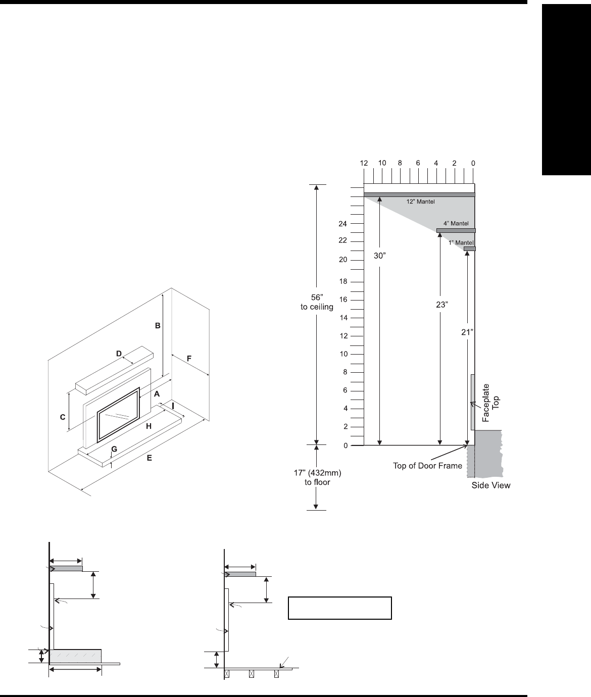
COMBUSTIBLE MANTEL
CLEARANCES
Because of the extreme heat this fi replace emits, the mantel clear-
ances are critical. Combustible mantel clearances from top of door frame
are shown in the diagram below. Mantel may be installed anywhere in the
shaded area or higher.
Note: A non-combustible mantel may be installed at a lower
height.
Note: Ensure the paint that is used on the mantel and the facing is
“heat resistant” or the paint may discolour.
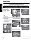
Unless otherwise stated the clearances listed below are Minimum distances
to combustible materials. Please Note: A major cause of chimney
related fi res is due to a failure to maintain required clearances (air
space) to combustible materials. It is of the greatest importance
that this insert and vent system be installed only in accordance with
these instructions.
Faceplate
12” Min.
Hearth
Mantel
C
12" Max.
D
Existing or
Non-Combustible Hearth
Top o f
Door Frame
G
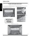
INSTALLATION WITH NON-COM-
BUSTIBLE HEARTH IN FRONT
INSTALLATION WITH COMBUSTIBLE
FLOORING IN FRONT
Faceplate
Combustible
Flooring
Mantel
C
12" Max.
D
Top of
Door Frame
4” min
Diagram 1
No hearth required if the unit
is raised 4" (102mm) or more.