


Regency
®
L234 Direct Vent Gas Insert
20
INSTALLATION
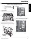
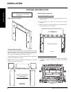
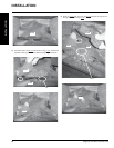
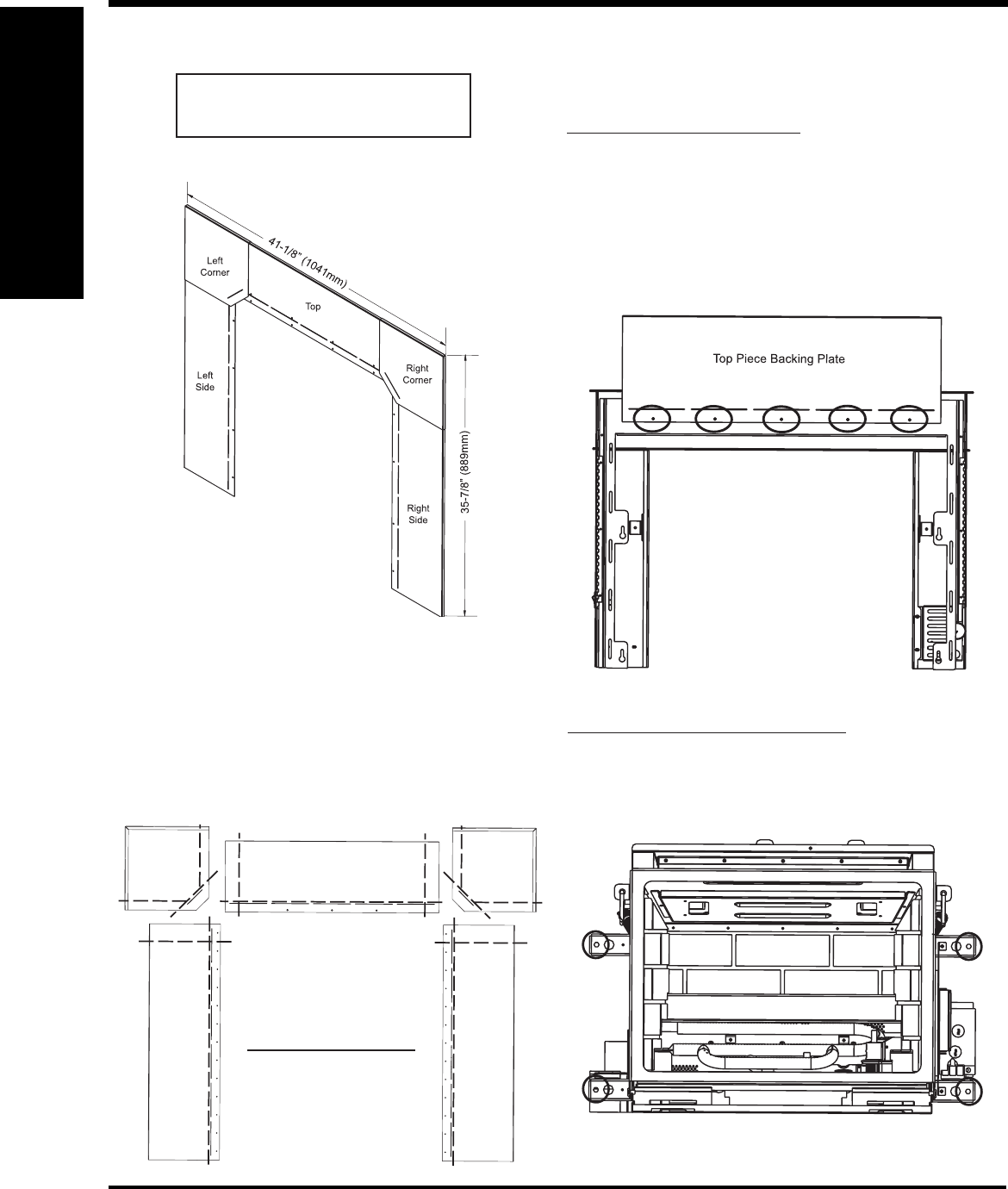
OPTIONAL BACKING PLATE
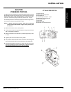
3) Attach the top piece of the backing plate to the faceplate using 5
screws provided as shown in diagram 1.
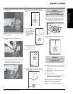
Rear View of Faceplate
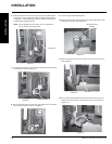
Attach Faceplate & Top Backing Plate to Unit
4) Place the 4 10-24 x 1/2" screws into the faceplate mounting brackets
as identifi ed in diagram 2. Screws are provided with faceplate
packaging.
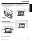
Backing Plate Assembly:
Attach Top Backing Plate to Faceplate
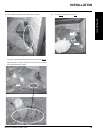
1) Remove the faceplate (Contour or Contemporary) from the unit if
already installed.
2) Lay the faceplate on its front, on a soft surface to prevent
scratching.
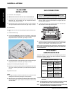
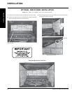
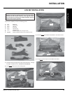
Backing Plate Installation:
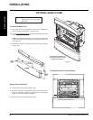
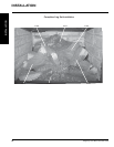
Customize Backing Plate:
The inside of the backing plate
may be cut as required using a
metal cutting blade.
Do not cut the outside edges.
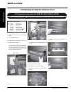
The Backing Plate can be adjusted to custom fi t an installation by trimming
the inside of the top, corner and side pieces as shown in the diagram
below. The dotted lines shown are only an example of where you can
cut. Cuts can be made beyond these marks as required.
Trim the backing plate using a metal cutting blade. No cut edges will be
exposed once installation is complete.
NOTE: In place of where any existing screw holes are cut, new holes
will need to be drilled for attachment.
Rear View of
Backing Plate
Backing Plate Contents List:
9 Screws (#8 x 1/2" Type B Black)
1 Backing Plate
Diagram 1
Diagram 2
INSTALLATION